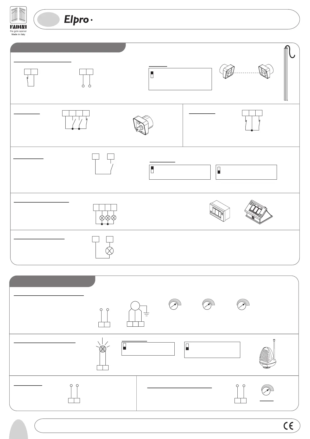
Photocells and Safety Edge:
1
2
PHOTOCELLS
AND SAFETY EDGE
12 13
24V (500 mA) OUTPUT (MAX. LOAD:
2 PAIRS PHOTOCELLS
1 RADIO RECEIVER)
Light ON = Open gate
Light OFF = Close gate
Flashing (fast) 0.5s= Closing gate
Flashing (normally) 1s= Opening gate
Flashing (slowly) 2s= gate is stopped
24V 3W Indication Light:
3
11
26
27
28
3
COMMON
Push Button Switch Pulin 3:
Led to indicate status of
Open - Stop - Close switches
1
DIP-SWITCH 1:
ON: Photocells stop gate while opening,
reverse it once obstacle is removed on closing
OFF: Photocells do not stop gate while
opening, reverse it in case of an
obstacle on closing
Button switch:
3
4
5
6
STOP
COMMON
OPOEN
CLOSE
COMMON
RADIO
CONTACT
7
3
Radio Contact:
- Open/Close (Standard)
- Travel reversing on pulsing
- Step by step
2
ON: Gate is not reversed while opening
OFF: Any pulse reverses the gate
DIP-SWITCH 2 and 5 (NEVER set BOTH of them ON at the same time):
Limit switch:
LIMIT SWITCH
CLOSE
COMMON
10
8
9
LIMIT SWITCH
OPEN
Flashing lamp 230V max 25W:
Power supply:
Capacitor and Single-phase Motor:
-
+
T1
MOTOR RUN TIME
OPEN/CLOSE
from 2 up to 255s
T2
-
+
DWELL TIME
from 2 up to 255s
230V
±10% MOTOR
2324
EXT Capacitor
20µF(fitted)
COMMON
M
16
14
15
17
18
19
20
POWER SUPPLY
230V ±10% 50Hz
SINGLE-PHASE
7
ON: Lamp is not operating during
Dwell time. Automatic mode.
OFF: It flashes during Dwell Time.
Automatic Mode.
4
ON: Pre-flashing
OFF: No pre-flashing
DIP-SWITCH 4 and 7:
T5
-
+
MOTOR
TORQUE
from 40% up to 100%
Courtesy Light 230V max 100W:
22 21
Trimmer T3
from 2s up to 255s
-
+
FADINI
l'apricancello
LOW VOLTAGE ELECTRICAL CONNECTIONS
6
4136
Drwg. No.
PLUS
15
GB
SINGLE-PHASE CONTROL PANEL WITH
MICROPROCESSOR FOR GIRRI 130 SLIDING GATE OPERATOR
ELECTRICAL POWER CONNECTIONS
ON: Step by step. Stop in between
OFF: Standard operating mode
5
®