d. Reinstall pushbar endcap.
L Do not force endcap. If endcap does not t easily, verify
that the switch clip is oriented correctly and the pin is in the
correct slot (step 6b).
c
a
b
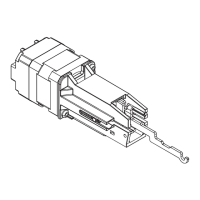
7 Attach wiring to terminal blocks on exit alarm kit board
as shown.
L Notes about Wiring:
The EI (external inhibit) option uses NO (normally open) dry contacts
to inhibit the exit alarm.
Closing the access control contacts inhibits the exit alarm. When the
access control contacts are re-opened, the exit alarm re-arms with
no delay.
RX, LX, and EI inputs are not polarized.
Gray
Black
Violet
Von Duprin 24 VDC
Power Supply
(Polarity Sensitive Input)
Insulate
unused
wire
EPT 10
24VDC
RX/LX
Switch
EI
EI
NO (normally open)
Access Contol
Contacts
NC
C
NO
D
J
F
Yellow
Red
Blue
RX Switch
Prior to 2012, the RX wires were
Red/Yellow/Blue
(use Red and Yellow).
*
*
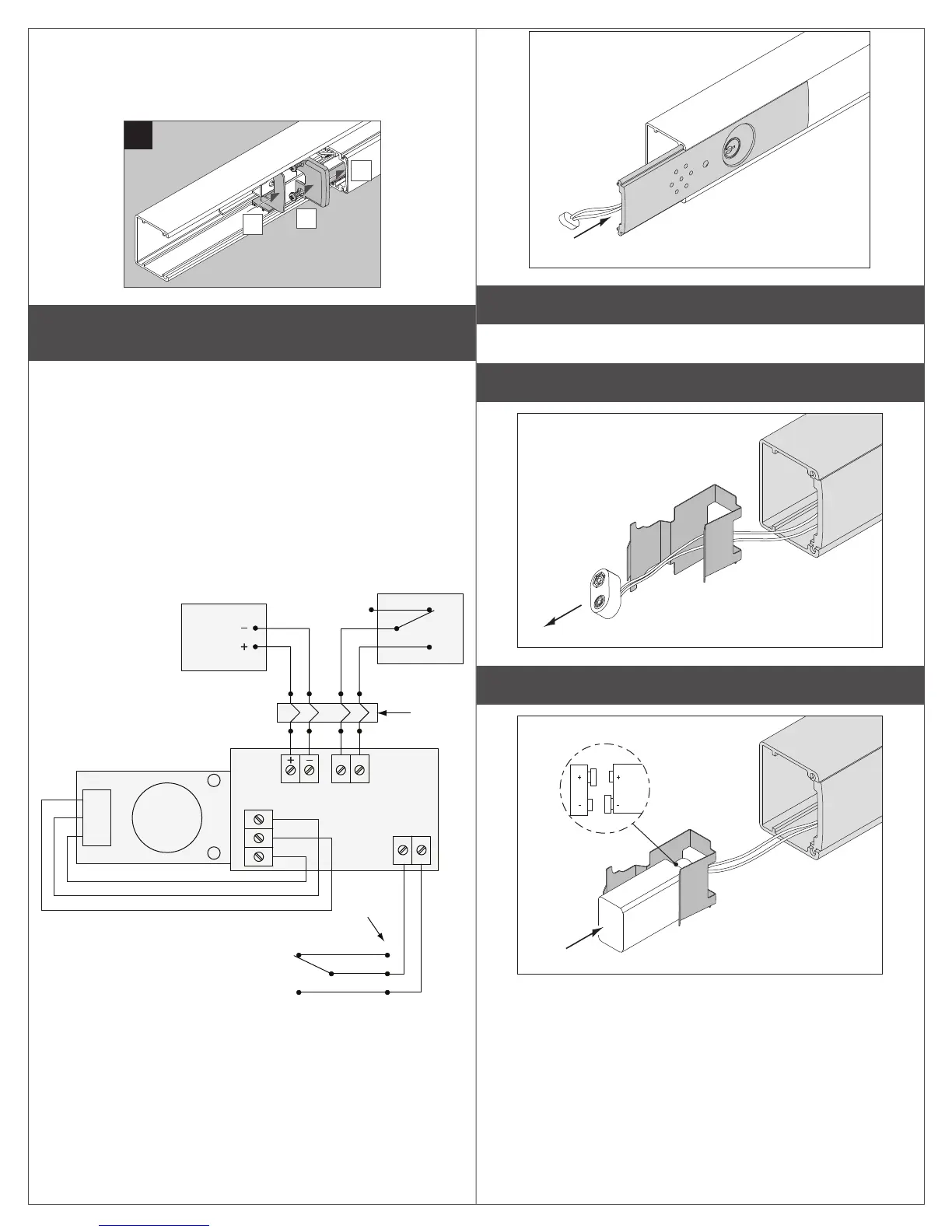
L Install exit alarm assembly in exit device.
8 Reinstall exit device onto door as needed.
9 Slide battery plug through battery holder.
10 Slide battery onto holder.
Make sure
polarity
is correct
 Loading...