16
FUMES DISCHARGE (only intended for personnel qualied to assemble the hood)
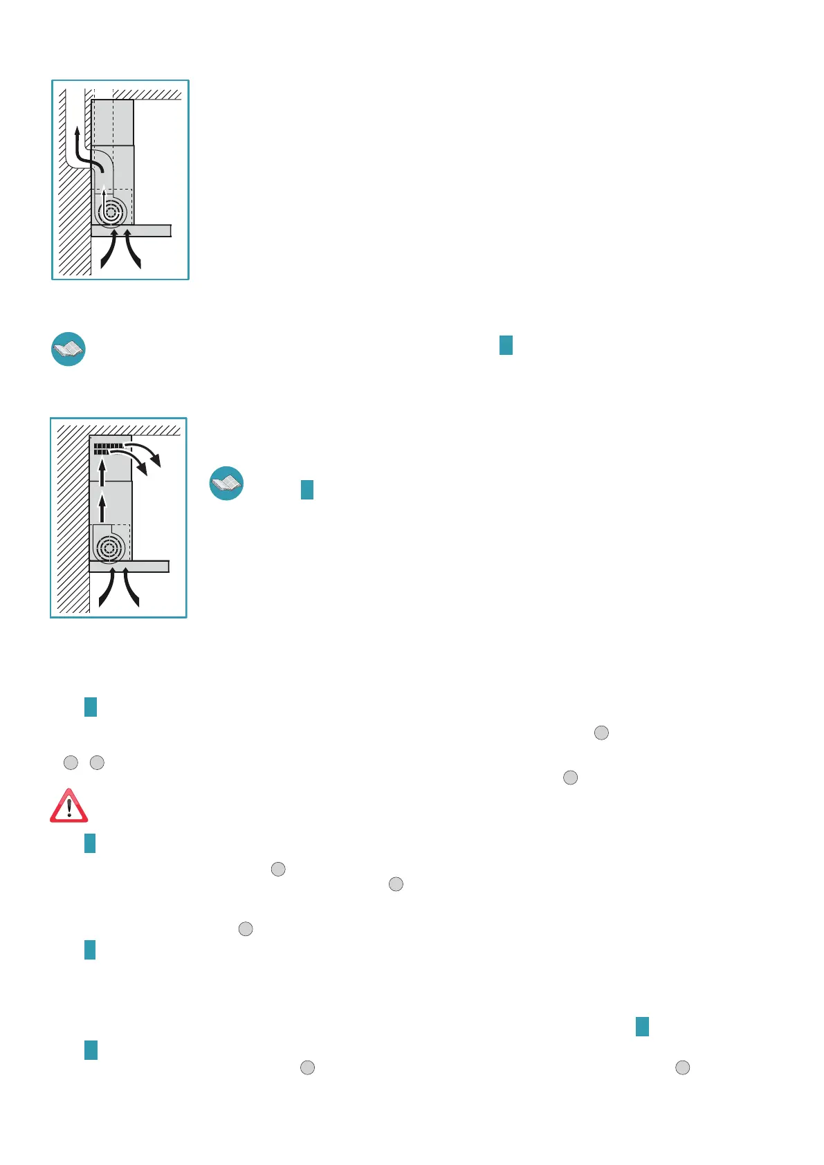
EXTERNAL EXHAUST HOOD VERSION SUCTION
In this version, the kitchen fumes and vapours are conveyed outside through an exhaust pipe.
The air outlet fitting that extends from the upper part of the hood must be connected with the pipe that conducts
the fumes and vapours to an external output.
Do not connect the equipment to discharge pipes of fumes produced from combustion (for example boil-
ers, replaces, etc) and you are to comply with the regulations in force regarding external air discharge.
The fumes outlet pipe must have:
- a diameter not less than that of the hood fitting;
- a slight slope downwards (drop) in the horizontal sections to prevent any formation of condensation from flowing
back to the hood;
- the minimum required number of bends;
- minimum required length (long pipes with various bends can reduce suction performance of the hood).
If the fumes outlet pipe passes through cold environments such as attics, etc., it is possible that water condensation
forms due to sudden changes in temperature. In this case, you are required to insulate the pipes.
When the kitchen hood is used simultaneously with other appliances that use gas or other fuels, the room must have sucient ventila-
tion, in accordance with regulations in force.
The active carbon filters in this version are to be removed. Refer to the instructions G on page 6 for removal.
Deviation for Germany: when the kitchen hood is used at the same time as appliances that are powered by energy other than electricity, the negative pressure
in the room must not exceed 4 Pa (4 x 10⁻⁵ bar).
HOOD VERSION WITH INTERNAL RECIRCULATION FILTERING
In this model, air passes through the active carbon filters to be purified and is then recycled into the kitchen envi-
ronment.
Check that the active carbon filters are assembled onto the hood, if not, install them as indicated in the in-
structions
G on page 6.
ASSEMBLY INSTRUCTIONS (only intended for personnel qualied to assemble the hood)
Phase
A page 4
• Place the support bar (S) on the installation wall at a height (H) from the cooker indicated in the figure (Fig.
1
).
• Use a spirit level to check the horizontal alignment and draw 2 marks at each end of the support bar, this is where the holes will be drilled (Fig.
2
-
3
).
• Drill the holes, insert 2 expansion plugs (ø 8mm) and fasten the bar with the relative screws (V1) (Fig.
4
).
The xing kit (screws, plugs, and brackets) supplied with the hood can only be used on masonry walls: should it be necessary to
install the hood onto walls in a different material, assess other fixing systems keeping the wall resistance and weight of the hood in mind
(indicated on page 2).
Phase
B page 4
• Hook the hood onto the support bar (Fig.
1
).
• Adjust the alignment of the hood by using the fixing screws (Fig.
2
). The upper screw (B) adjusts the distance from the wall, the lower one (C)
adjusts vertical scrolling.
• To prevent the hood from falling due to a pressure below, fasten it to the wall with expansion plugs and relative screws (V2) using the appropriate
holes on the back of the hood (Fig.
3
).
Phase
C page 4
EXTERNAL EXHAUST HOOD VERSION SUCTION
• Connect the air outlet connection of the hood to the external discharge with a suitable pipe.
HOOD VERSION WITH INTERNAL RECIRCULATION FILTERING
• Check that the active carbon filters are assembled onto the hood, if not, install them as indicated in the instructions H on page 6.
Phase
D page 5
• Insert the extension (H) in the chimney (G) (Fig.
1
) and fasten the assembly to the body of the hood using screws (V3)(Fig.
2
).
• With external exhaust (suction) versions, it is possible to insert extension (H) with the slots facing downwards so that they are not visible when
the installation height allows it.