7. Connect the power wire “+” to the “+” side of your battery connector (wired type battery), or to the “+” connector going to
the “+” side of your battery (inboard bullet type battery). We highly recommend marking the “+” wire with a short piece of red
heat shrink tube, to help avoid mistakenly plugging the “+” connector into the “-“ side of the battery, which will cause immediate
damage to the ESC, which is not covered under warranty.
Connect the power wire “-” to the “-” side of your battery connector (wired type battery), or to the “-” connector going to the “-”
side of your battery (inboard bullet type battery).
Important Tips:
1. Avoid soldering longer than 5 seconds per solder joint, when replacing the power wires on the ESC. Prolonged heat from
the soldering iron can cause permanent damage to the circuit board, which is not covered under warranty.
2. The BEC wire is only used to connect the ESC to the radio receiver. To connect the ESC to the LCD Program Card, you
must use the signal cable that is included with the LCD Program Card.
3. We recommend using the fan for the best protection and performance. Excess heat can cause permanent damage to the
internal components and/or premature failure, which is not covered under warranty. Also, excess heat increases the
electrical resistance of the ESC, which in turn lowers the performance capability.
WWW.FANTOMRACING.COM
ESC USERS MANUAL
• FR-10 PRO ESC
• 25mm Fan
• Machined aluminum fan cover
• 2 x 165mm Input Wires - 11awg / 2,303 strand super-flex high performance wire (pre-soldered on ESC)
• 3 x 165mm Output Wires - 11awg / 2,303 strand super-flex high performance wire (pre-soldered on ESC)
• 3 Integrated Max Power Capacitors
• Shrink Tube w/ Fantom logo
• Red shrink tube for marking positive battery wire
1. Mount the ESC in your vehicle, using double-sided tape, in the location recommended in your vehicle’s instruction manual.
We recommend using 3M® brand double-sided tape.
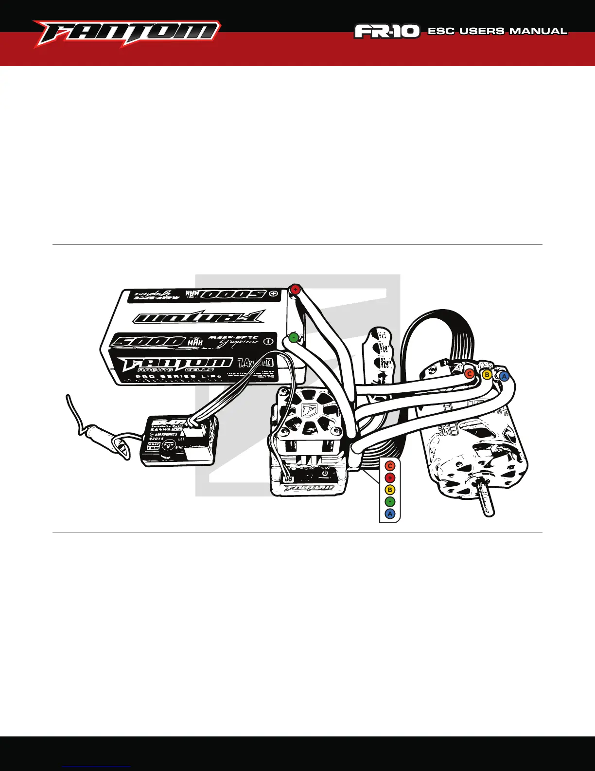
2. Connect the speed control BEC connector (3 small black wires) into channel 2 of the receiver. Make sure to pay close
attention to polarity. The BEC connector has two beveled edges, that should match most brand’s receiver input plug.
3. Solder the power wire “A” to the motor “A” solder-tab.
4. Solder the power wire “B” to the motor “B” solder-tab.
5. Solder the power wire “C” to the motor “C” solder-tab.
6. Connect the hall sensor cable (sold separately) to the speed control (underneath the solder tabs) and to the motor’s sensor
cable port. Make sure to pay close attention to the orientation. Both sensor cable connectors have “ears” that must match
the orientation of the notches in the sensor ports.
INCLUDED IN BOX:
CONNECTION DIAGRAM:
INSTALLATION:
 Loading...