SAFETY PRECAUTIONS B-83144EN/01
s - 4
(2) Even when the robot is stationary, it is possible that the robot is still in a ready to move state, and is
waiting for a signal. In this state, the robot is regarded as still in motion. To ensure working person
safety, provide the system with an alarm to indicate visually or aurally that the robot is in motion.
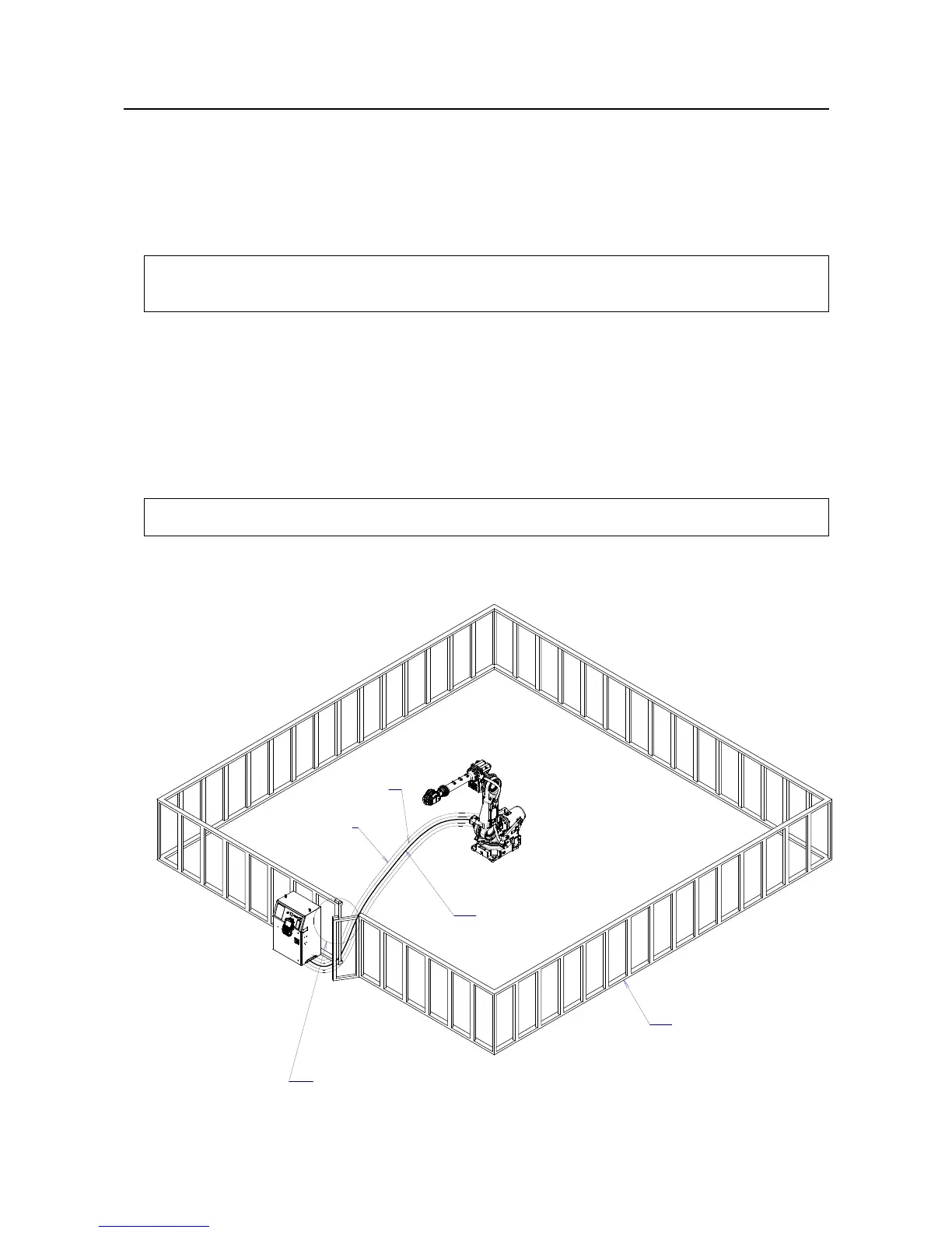
(3) Install a safety fence with a gate so that no working person can enter the work area without passing
through the gate. Install an interlocking device, a safety plug, and so forth in the safety gate so that the
robot is stopped as the safety gate is opened.
The controller is designed to receive this interlocking signal of the door switch. When the gate is
opened and this signal received, the controller stops the robot in an emergency. For
connection, see Fig.1.2 (a) and Fig.1.2 (b).
(4) Provide the peripheral devices with appropriate grounding (Class A, Class B, Class C, and Class D).
(5) Try to install the peripheral devices outside the work area.
(6) Draw an outline on the floor, clearly indicating the range of the robot motion, including the tools such
as a hand.
(7) Install a mat switch or photoelectric switch on the floor with an interlock to a visual or aural alarm that
stops the robot when a working person enters the work area.
(8) If necessary, install a safety lock so that no one except the working person in charge can turn on the
power of the robot.
The circuit breaker installed in the controller is designed to disable anyone from turning it on
when it is locked with a padlock.
(9) When adjusting each peripheral device independently, be sure to turn off the power of the robot.
RM1
Motor power/brake
RP1
Pulsecoder
RI/RO,XHBK,XROT
EARTH
Safety fence
Interlocking device and safety plug that are activated if the
gate is opened.
Fig. 1.2 (a) Safety Fence and Safety Gate
 Loading...