B-83144EN/01 SAFETY PRECAUTIONS
s - 5
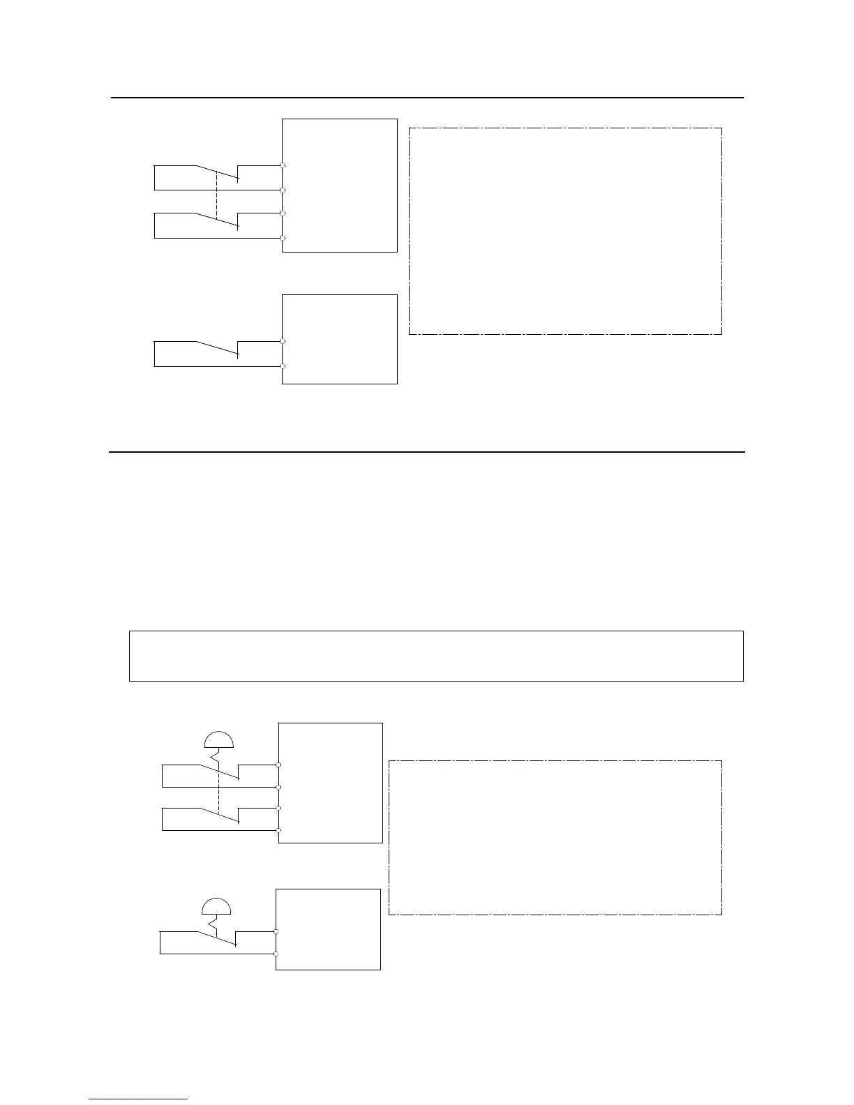
Dual chain
Single chain
Panel board
FENCE1
FENCE2
Panel board
EAS1
EAS11
EAS2
EAS21
(Note)
In case of R-30iA
Terminals EAS1,EAS11,EAS2,EAS21 or FENCE1,FENCE2
are provided on the operation box or on the terminal block
of the printed circuit board.
In case of R-30iA Mate
Terminals EAS1,EAS11,EAS2,EAS21 are provided
on the emergency stop board or connector panel.
(in case of Open air type)
Termianls FENCE1,FENCE2 are provided
on the emergency stop board.
Refer to controller maintenance manual for details.
Fig.1.2 (b) Connection Diagram for Safety Fence
1.2.1 Operator Safety
The operator is a person who operates the robot system. In this sense, a worker who operates the teach
pendant is also an operator. However, this section does not apply to teach pendant operators.
(1) If you do not have to operate the robot, turn off the power of the robot controller or press the
EMERGENCY STOP button, and then proceed with necessary work.
(2) Operate the robot system at a location outside of the safety fence
(3) Install a safety fence with a safety gate to prevent any worker other than the operator from entering the
work area unexpectedly and to prevent the worker from entering a dangerous area.
(4) Install an EMERGENCY STOP button within the operator’s reach.
The robot controller is designed to be connected to an external EMERGENCY STOP button.
With this connection, the controller stops the robot operation when the external EMERGENCY
STOP button is pressed. See the diagram below for connection.
Dual chain
Single chain
(Note)
Connecto EES1and EES11,EES2 and EES21or EMGIN1and EMGIN2.
In case of R-30iA
EES1,EES11,EES2,EES21 or EMGIN1,EMGIN2 are on the panel board.
In case of R-30iA Mate
EES1,EES11,EES2,EES21 are on the emergency stop board
or connector panel (in case of Open air type),.
EMGIN1,EMGIN2 are on the emergency stop board.
Refer to the maintenance manual of the controller for details.
External stop button
Panel board
EMGIN1
EMGIN2
Panel board
EES1
EES11
EES2
EES21
External stop button
Fig.1.2.1 Connection Diagram for External Emergency Stop Button
 Loading...