B-82604EN/01 SAFETY 1.SAFETY PRECAUTIONS
- s-7 -
1.1.1 Operator Safety
The operator is a person who operates the robot system. In this
sense, a worker who operates the teach pendant is also an operator.
However, this section does not apply to teach pendant operators.
(1) If it is not necessary for the robot to operate, turn off the power
of the robot controller or press the EMERGENCY STOP button,
and then proceed with necessary work
(2) Operate the robot system at a location outside the work area.
(3) Install a safety fence with a safety gate to prevent any worker
other than the operator from entering the work area unexpectedly
and also to prevent the worker from entering a dangerous area.
(4) Install an EMERGENCY STOP button within the operator's
reach.
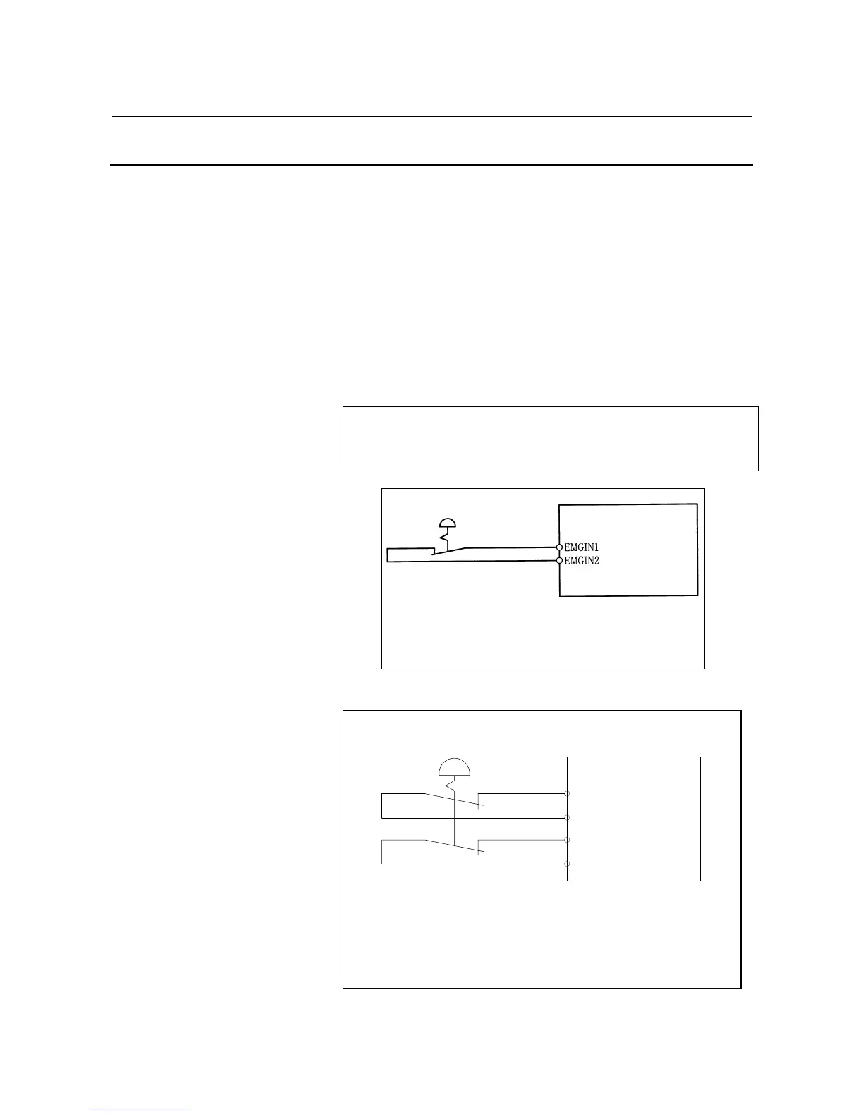
The robot controller is designed to be connected to an external
EMERGENCY STOP button. With this connection, the controller stops the
robot operation when the external EMERGENCY STOP button is pressed.
See the diagram below for connection.
External EMERGENCY
STOP button
Panel board
Note) Connect between EMGIN1 and EMGIN 2.
Terminals EMGIN1 and EMGIN2 are on the
Panel board.
Fig.1.1.1(a) Connection Diagram for External Emergency Stop Switch
(For R-J3iB CONTROLLER)
パネルボード
EES1
EES11
EES2
EES21
(注) EES1-EES11間、 EES2-EES21間に接続します。
EES1,EES11、EES2,EES21はパネルボード上にあり
ます。
詳細はR-J3iC制御部保守説明書をご参照下さい。
外部非常停止スイッチ
External EMERGENC
STOP button
Panel board
Fig.1.1.1(b) Connection Diagram for External Emergency Stop Switch
(For R-30iA CONTROLLER)
Note) Connect between EES1 and EES11 and between EES2 and
EES21. Terminals EES1, EES11, EES2 and EES21 are on
the Panel board. Refer to R-30i
 Loading...