III- 2
Step 2.) B.) Use four #10 lag screws (not supplied) to
secure the control unit to the wall.
NOTE: The screw type may be required to be
different depending on the wall
material.
The screw type and length must
support up to 35 lbs.
(control unit, options and battery set).
C.) If the control unit is to be mounted
semi-flush, the backbox can be mounted
up to 3.5" into the wall.
Place the 15216 Semi-flush Trim around
the backbox and affix to the wall with four
#10 x 3/4" wood screws (P/N 940454).
NOTE: The screw type may be required to be
different depending on the wall
material.
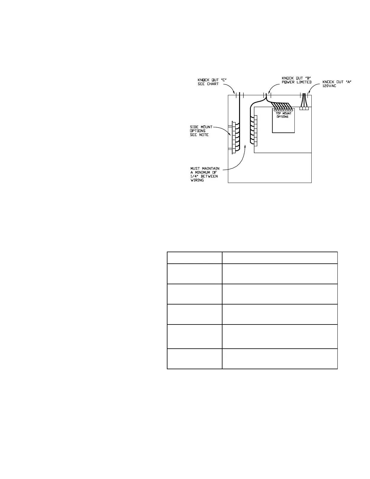
Step 3.) Attach conduit (if required) and run wires as
required. Do not connect wires at this time.
Non power limited field wires must be run in
separate conduit and be 1/4" from power
limited wires.
1.) 120VAC power use knock out "A".
2.) Main panel and top mount options use
knock out "B".
3.) Side mount option wiring use knock out "C"
(see chart).
SIDE OPTION NOTES
15209
All field wiring must be power limited to
module
15215
(Local Energy)
All field wiring must be non power limited to
module
15215
(Remote Station)
All field wiring must be power limited to
module
15217
Wiring may be either all power limited or all
non power limited. The 2 types cannot be
mixed together.
15206
All field wiring must be power limited to
module