III- 1
INSTALLATION INSTRUCTION AND WIRING FOR
CAT NO. 15220A OR 15240A FIRE ALARM CONTROL UNIT
The 15220A, Two Zone, and 15240A, Four Zone, Fire Alarm System Control Unit provides manual,
automatic, and waterflow alarm and supervisory service. Zone #1, may be used as a manual, auto-
matic, or waterflow initiating circuit or it can be programmed to be used with normally open sprinkler
supervisory switches. Zone #2 may be used as a manual, automatic, or waterflow initiating circuit and
can also be programmed to be non-silencable for use with waterflow switches, if required. The control
unit has one signal circuit capable of operating up to a total of 2.5A. of U.L. listed compatible signals.
The control unit also provides up to 0.3A. of resetable 19-28VDC power for U.L. listed compatible 4-
wire smoke detectors. The integral battery charger is capable of charging up to a 15 A.H., 24VDC
battery set and is supervised for a disconnected, shorted, or low (below 23VDC) battery set. Other
standards features include ground detection, signal silencing, subsequent alarm signaling, automatic
short circuit disconnect on the signal circuit and trouble buzzer ring back.
Step 1.) Installation is to be done only by qualified
personnel who have thoroughly read and
understood this instruction sheet.
CAUTIONS:
1.) It is recommended that the main board be
removed for any procedure that may cause dust,
metal shavings, grease or any such matter that
may affect the circuit board and/or parts.
2.) There may be several sources of power
into the control unit. Each source must be
disconnected prior to installing or removing
modules, connecting or disconnecting wiring,
and cutting out programming diodes and
jumpers.
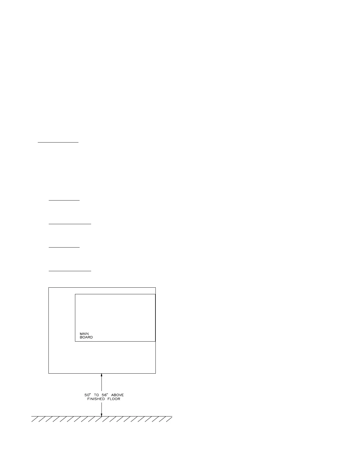
Step 2.) A.) The control unit should be located
near an exit at ground level, where the
normal ambient temperature is maintained
within the control unit specification. (See
General Specifications), Also, in a area that
is free of dust, vibration, moisture and
condensation. Mount the control unit at a
convenient height for viewing indicators and
operating switches, approximately 50" to 56"
above the finished floor to the bottom of
the backbox.
Parts Supplied
4 942665 3.9K ohm 1/2w. Resistor
2 942666 47K Ohm 1/2w. Resistor
4 29529-114 #6-32 x 3/8" Screws
4 18965 #6-32 Keps Nut
6 J010575 Receptacle, Crimp-on
1 445927 Operating Instructions
1 445926 Owners Manual
For 15220A
1 413266 Control Unit 15220A
1 413306 Door Assembly 15220A
For 15220A-240
1 413267 Control Unit 15220A-240
1 413306 Door Assembly 15220A-240
For 15240A
1 413268 Control Unit 15240A
1 413308 Door Assembly 15240A
For 15240A-240
1 413269 Control Unit 15240A-240
1 413309 Door Assembly 15240A-240
CONTROL UNIT MOUNTING DIAGRAM