III- 10
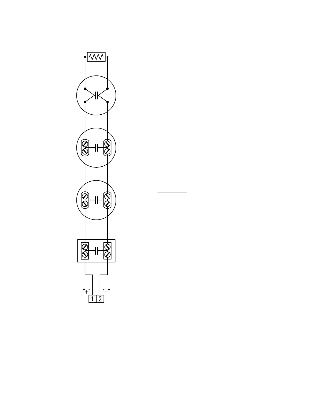
TYPICAL INITIATING DEVICE WIRING DIAGRAM
HEAT DETECTORS AND PULL STATIONS
Notes:
1.) This wiring diagram only shows general
information about the initiating device. For
specific wiring and installation information
read the instructions provided with each
device.
2.) For initiating circuit specifications see the
15220A Wiring Diagram (445928) or the
15240A Wiring Diagram (445929).
END OF LINE RESISTOR
(3.9K OHM 1/2 WATT)
NON-CODE PULL STATIONS
FARADAY CAT. NO.
F1GT, F1GGT, F1GHT
PM6700, PM6608, PM6696,
PM6695, PM6699
HEAT DETECTORS
FARADAY CAT. NO.
9300-136, 9300-190, 9341-136,
9342-190, 9343-136, 9344-190,
9345-136, 9345-190, 9347-136,
9348-190,
PM2872-136, PM2872-190,
PM2872F-136, PM2872F-190
CHEMETRON CAT. NO.
A-135, A-200, AT-135, AT-200.
601, 602, 603, 604,
621, 622, 623, 624,
EPB501, EPB502, EPB503, EPB504
OR ANY U.L. LISTED
N.O. CONTACT INITIATING
DEVICE WITH COMPATIBLE
RATINGS
INITIATING
CIRCUIT