III- 36
Alarm Ratings:
2.5A. max.
(combined circuit #1 + #2)
Use only compatible signals
specified in owners manual.
F
I
R
E
F
I
R
E
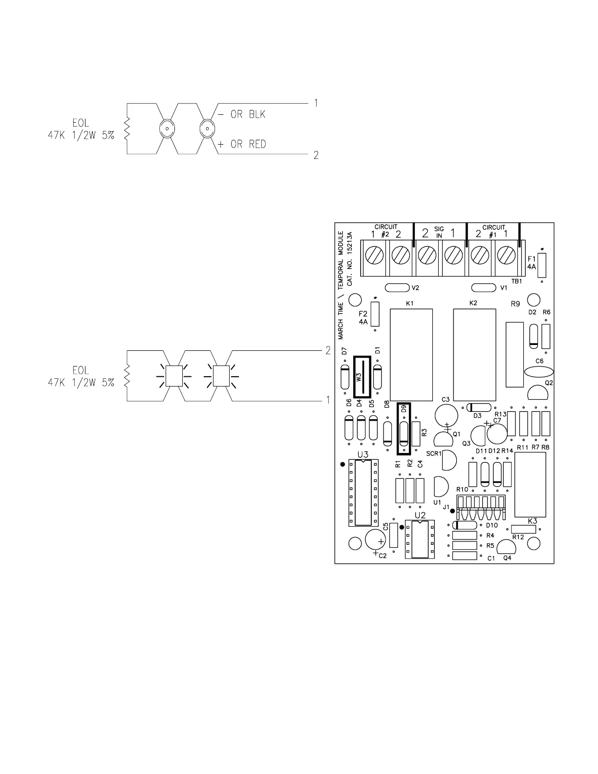
- OR BLK
+ OR RED
See
Note #5
NOTES
1.) Units to be installed in accordance with the
National Electrical Code and / or local electrical
codes.
2.) See the Signal Circuit Wire Selection Guide to
determine wire size.
3.) Terminal block will accept a maximum of
#14 AWG wiring or .260" spade terminals.
Terminal block screw size is #6-32.
4.) See the owners manual for compatible signals.
5.) Signal circuit terminals 1 and 2 on the main board
must be wired to signal in terminals 1 and 2,
respectively, on the March Time/Temporal
signaling module. No other circuits can be
connected to these terminals.
6.) Circuit #1 and circuit #2 must be run together to
the same notification area.
CIRCUIT #1
POWER LIMITED
SUPERVISED
CIRCUIT #2
POWER LIMITED
SUPERVISED