III- 37
Step 1.) Installation is to be done only by qualified
personnel who have thoroughly read and
understood this instruction sheet.
Step 2.) Disconnect all power into system, including
batteries.
Step 3.) Remove L.E.D. indicator mask from main board.
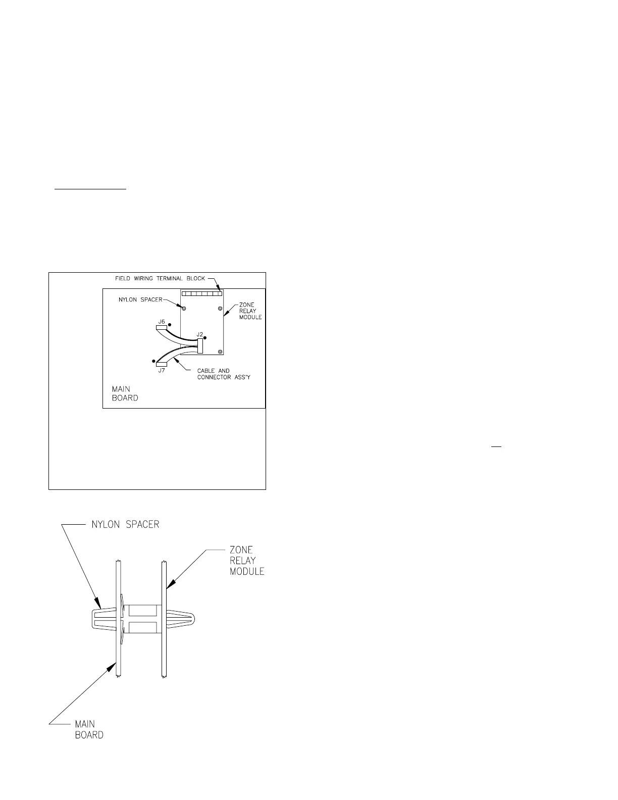
Step 4.) Install module onto main board.
A.) Place four nylon spacers (P/N 942456) into
mounting holes on the main board.
B.) Mount module with terminal block at the top.
NOTE: Main board connector J3 must be straight
to feed through back of the module.
C.) Plug cable and connector ass'y (P/N 444729)
into the module connector J2 and main board
connectors J6 & J7 with the colored rib on the
dot at each connector.
NOTE: J7 is not used on 15220(A) control units.
CAUTION: Check to see that the connectors are
properly seated on all of the pins.
Step 5.) If zone #1 is used for sprinkler supervisory
switches, diode D1 must be cut out of the
module.
Step 6.) Connect field wires as required.
Step 7.) Apply power to system.
Step 8.) Check for proper operation of module functions.
Step 9.) Replace L.E.D. indicator mask on main board.
Module Mounting Diagram
INSTALLATION INSTRUCTIONS AND WIRING FOR
CAT. NO. 15219 ZONE RELAY MODULE
The 15219 Zone Relay Module is an optional module for the 15220(A) or 15240(A) Fire Alarm System Control
Unit. This module provides a form "A" zone alarm contact per zone, a form "A" general alarm contact, and a
form "B" general alarm contact.
444734 - Rev. A
Parts Supplied
1 15219 Zone Relay Module
4 942456 Nylon Spacer - 5/8"
1 444729 Cable and Connector Ass'y
1 444734 Instruction Sheet