3
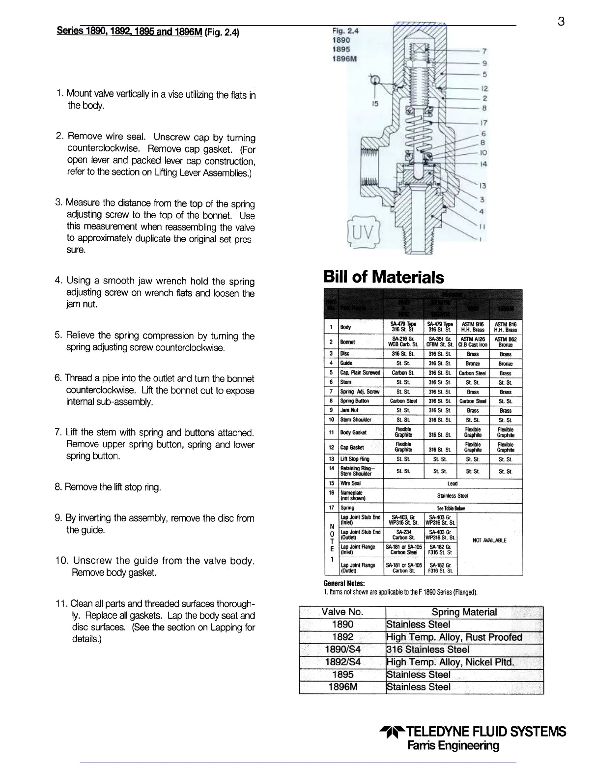
Series 1890. 1892. 1895 and 1896M (Fig. 2.4)
1. Mount valve vertically in a vise utilizing the flats in
the body.
2. Remove wire seal. Unscrew cap by turning
counterclockwise. Remove cap gasket. (For
open lever and packed lever cap construction,
refer to the section on Lifting Lever Assemblies.)
3. Measure the distance from the top of the spring
adjusting screw to the top of the bonnet. Use
this measurement when reassembling the valve
to approximately duplicate the original set pres-
sure.
Bill of Materials
4. Using a smooth jaw wrench hold the spring
adjusting screw on wrench flats and loosen the
jam nut.
SA.479 Type I SA-419 Type
316 St. 51 316 51. 51.
5. Relieve the spring compression by turning the
spring adjusting screw counterclockwise.
316 St SI I 316 SI. St
316 SI. St.StSt.
CaIIIon St.
St. St.
St 51
1 I!Orjy
",," ,
2 Bonnet
~~~-, ~~
3 ~ c
4 Glide St St.
5 ~, Plain ~ CaIIIon St.
6 Sf8m St. St.
7 Sprilg Adj. Screw St. St.
8 SpIi1O BIIt1On ..-c
9 Jam Nut St St
10 Smm ShOtJkIer St St
11 Body Gasket =~
12 Cap GasI<et =I:e
13 Lift Slop Ring St St
14 Relainmg Ring- St St
Stem SOOWder .
15 Wire Seal
16 Namepmm
(not shown)
17 Spring
lap Joint Stub End
N (In~)
0 Lap Jamt Stub End ~234
T (OUllet) Carbon St
E Lap JoHrt Range ~181 or ~105
(Inlet) Carbon Steel
1
lap Joint Flange ~181 Qr SA-105
(O.l1et) CarbQrJ St
6. Thread a pipe into the outlet and turn the bonnet
counterclockwise. Lift the bonnet out to expose
intemal sub-assembly.
7. Uft the stem with spring and buttons attached.
Remove upper spring button, spring and lower
spring button.
8. Remove the lift stop ring.
9. By inverting the assembly, remove the disc from
the guide.
~. Gr SA-4O3 Gr
WP316 51 51 WP316 5t St.
SA-403 Gr
WP316 St. St.
SA-182 Gr.
F316 St 5t.
SA-152 Gr.
F316 5t. 5t.
NOT AVAILABLE
10. Unscrew the guide from the valve body.
Remove body gasket.
General Noles:
1 Items not shown are applicable to the F 1890 Series (Flanged).
11. Clean all parts and threaded surfaces thorough-
ly. Replace all gaskets. Lap the body seat and
disc surfaces. (See the section on Lapping for
details.)
Valve No.
1890
1892
1890/84
1892/84
1895
1896M
Spring Material
Stainless
SteelHigh
Temp. Alloy, Rust Proofed
316 Stainless SteelHigh
Temp. Alloy, Nickel Pltd.Stainless
SteelStainless
Steel
TELEDYNE FLUID SYSTEMS
Fanis Engineering
Visit www.boighill.com to request a quote.
Visit www.boighill.com to request a quote.
 Loading...