6
Series 1890. 1892. 1895 AND 1896
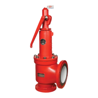
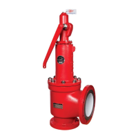
1. Refer to Figure 2.4 for construction details.
2. Visually inspect all parts to be assembled. Replace
gaskets, a-rings, and any parts that are worn.
Lubricate all threaded and mating surfaces with Bostik
Never Seez (or equivalent).
2. Visually inspect all parts to be assembled. Replace
all gaskets. Lubricate all threaded and mating sur-
faces with Bostik Never Seez ( or equivalent.).
3. Examine seat of body and disc for any marks that may
cause leakage. Refer to the section on lapping if
relapping is necessary.
3. Examine seat of body and disC for any marks or sur-
face imperfections that may neduce seat tightness.
If relapping is necessary, refer to the section on lap-
.I
ping. !
4. (O-ring Seat Only) Refer to Fig. 5.1. Position the
disc on a flat surface with the O-ring groove facing
up. Insert O-ring into the disc groove. Insert the
O-ring retainer on the disc, ensuring the O-ring is
centered. Lock the O-ring and retainer to the disk
with the hex nut.
4a.(Metal Seat Only) Loosely assemble body and
guide. Insert disc in guide and verify that guide
turndown from disc contact is 1/16 to 1/4 turn.
For set pressure under 100: PSIG, 1/8 turndown
maximum is required. Remo~e disc.
4b.(O-Ring Seat Only) It is ~ecommended that
O-ring/disc sub-assembly be replaoed rather than
attempt removal of retainin~ ring. Do not use a
metal seat guide in O-ring se~t seal valves.
5. Tighten the blowdown ring to the body.
6a. (1850, 1852, 1856M open lever and 1856M packed
lever only) Place stem retainer over stem. Screw
stem retainer to disc.
5. Tighten guide to body with 11/4" dia. bar inserted
through guide exit holes with qpproximate torque of
20 ft. Ibs.
6. Insert disc and install lift stop.
disc lift is greater than .085".
Verify that available
6b. (1855 only) Place stem into the disc. Drive groove pin
through the disc into the stem.
6c. (1856M Plain cap only) Insert retaining ring into the
stem groove. Place stem into disc.
7. Place disc- stem assembly over the body, making sure
that the disc and body seats are aligned.
7. Place stem shoulder over retaining ring. Install
spring and spring buttons on $tem and insert entire
assembly into bonnet/spring ~djusting screw sub-
assembly. The lower sub-a~sembly with bonnet
gasket can then be assembled and tightened to
approximately 40 ft. Ibs. torque.
8. Install lower spring button, spring and upper spring
button on stem.
9. Place bonnet over the assembled parts and screw
down onto the body.
8. Hand tighten adjusting screw until slight spring
compression occurs.
10. Thread the jam nut onto the spring adjusting screw.
11. Thread spring adjusting screw into bonnet to the posi-
tion recorded during disassembly.
12.The valve is now ready to be removed for testing.
Fig. 5.1 1850 Series O-Ring Seat Construction
Fig. 5.2 1890 Series O-Ring Seat Construction
TELEDYNE FLUID SYSTEMS
FarTis Engineering
Series 1850. 1852. 1855 AND 1856M
1. Refer to Figures 2..1- 2.3 for construction details.
Visit www.boighill.com to request a quote.
Visit www.boighill.com to request a quote.
 Loading...