9
8. Testing Procedures (continued)
Seat Leakage Test:
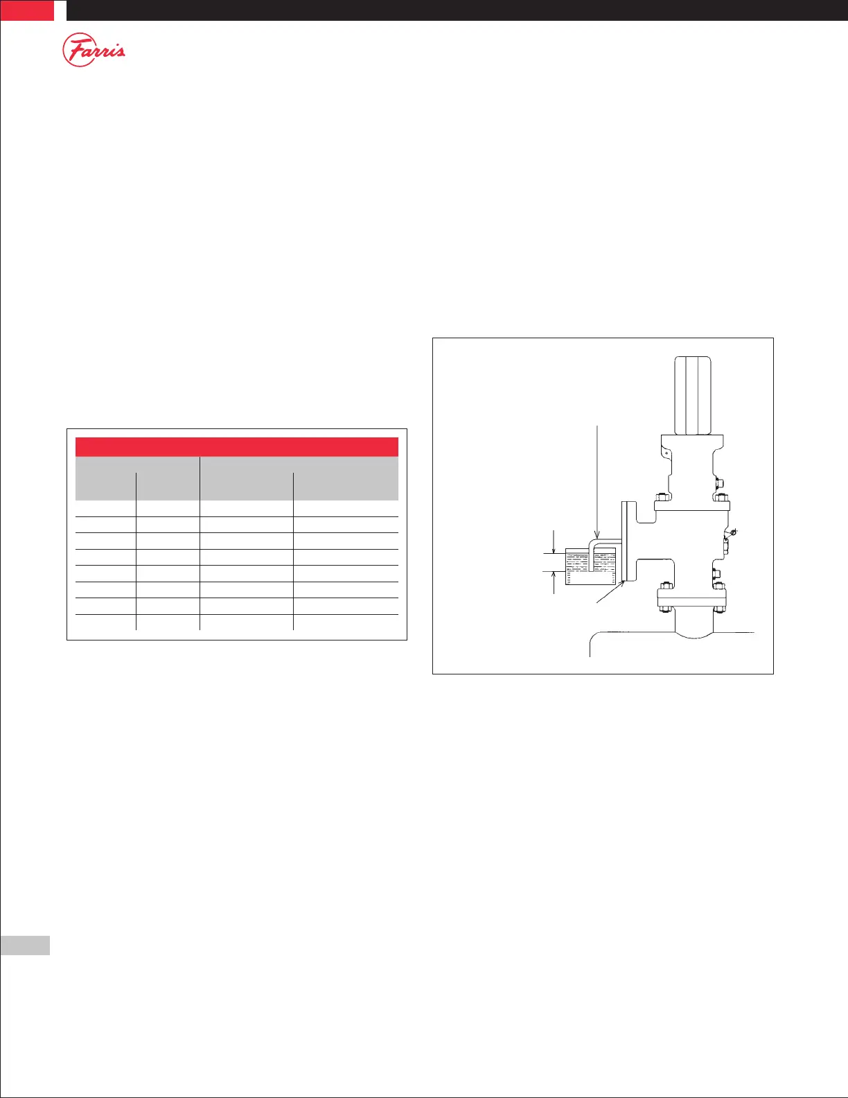
1. Next perform a seat leakage test. With the valve mounted on the test
stand, attach a blind flange test fixture as shown in Figure 6 (air, gas, &
vapor service valves only). For steam and water seat leakage testing,
see paragraphs 4 and 5.
2. For metal and soft seated valves the pressure is held at 90% of cold
differential test pressure when the CDTP is greater than 50 psig. For
CDTP 50 psig and below, the pressure should be held 5 psig below the
CDTP.
3. Bring the pressure up and hold it for one minute for valves up to 2" inlet
size, 2 minutes for valves from 2 1/2" to 4" inlet size, and 5 minutes for
valves with inlet sizes 6" and larger. Then count the number of bubbles
for one minute. The acceptance criteria for metal seat valves are per the
following table. For O ring and soft seat valves, there should be no
leakage (zero bubbles per minute).
Table 3
Seat Tightness: Air, Gas & Vapor Service
Set Pressure Leakage Rate in Bubbles Per Minute
psig barg Orifice Size ≤ 0.307
Sq. In (200 mm
2
)
Orifice Size < 0.307
Sq. In (200 mm
2
)
15 to 1000 1.03 to 68.9 40 20
1500 103 60 30
2000 138 80 40
2500 172 100 50
3000 207 100 60
4000 276 100 80
5000 345 100 100
6000 413 100 100
4. Steam: Test pressure per paragraph 2 shall be applied for 3 minutes
before the seat tightness test. The valve should be observed for leakage
for at least one minute. There should be no visible sign of leakage at the
valve outlet when viewed against a black background.
Where the Code allows ASME Section VIII steam valves to be tested on air,
seat leakage may be verified using the procedure for air, gas, and vapor
service valves as listed in paragraphs 1 to 3.
5. Water: Liquid valves are tested on water. Test pressures per paragraph
2 should be applied for a period of two minutes. There should be no
visible sign of leakage.
Note: When performing the seat leakage test on valves with open levers, a
plain screwed test cap must be used. This will prevent the venting of the
test pressure through the top of the bonnet.
Tube 5/16" (7.9 millimeters)
OD x 0.035 inch
(0.89 millimeter) Wall
Note: The cover plate should be fitted with a
suitable device to relieve body pressure in case
of accidental popping of the valve.
1/2" (12.7 millimeters)
WATER
AIR RECEIVER
Figure 6