EasyManuals Logo

Farris Engineering Curtiss-Wright 2600 Series User Manual

Farris Engineering Curtiss-Wright 2600 Series
12 pages
To Next Page IconTo Next Page
To Previous Page IconTo Previous Page
Page #6 background imageLoading...
Page #6 background image
5
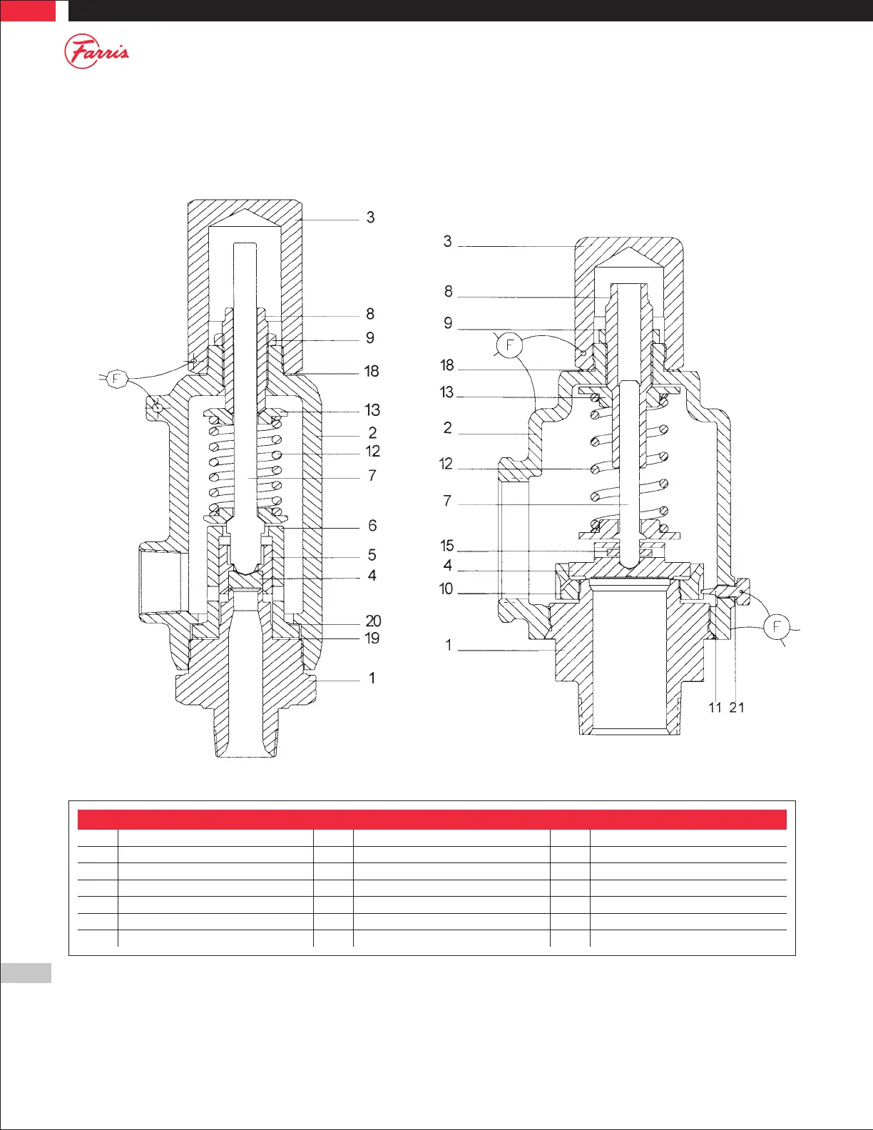
Figure 3: Parts List - Threaded Valves
1 Body 8 Spring Adjusting Screw 15 Grooved Pin
2 Bonnet 9 Jam Nut (Spr. Adj. Scr.) 16 Lift Stop Ring
3 Cap 10 Blow Down Ring 17 Retaining Ring, Stem Shoulder
4 Disc 11 Lock Screw (B.D.R.) 18 Cap Gasket
5 Disc Holder 12 Spring 19 Body Gasket
6 Guide 13 Spring Button 20 Guide Gasket
7 Stem 14 Stem Shoulder 21 B.D.R. Lock Screw Gasket
Series 2700 Series 2850 & 2856
Figure 3

Questions and Answers:

Question and Answer IconNeed help?

Do you have a question about the Farris Engineering Curtiss-Wright 2600 Series and is the answer not in the manual?

Farris Engineering Curtiss-Wright 2600 Series Specifications

General IconGeneral
BrandFarris Engineering
ModelCurtiss-Wright 2600 Series
CategoryControl Unit
LanguageEnglish

Related product manuals