7
Table 1
Part No. Grade Finish Size
18632X1 (055) 3F Roughing 1/2 oz. tube
18633X1 (075) 38-500 Medium 1/2 oz. tube
18634X1 (105) 38-1200 Final 1/2 oz. tube
7. Cleaning & Lapping
Each part should receive a visual examination for signs of wear and
corrosion. Parts that show signs of excessive corrosion or wear should be
replaced with genuine Farris Factory supplied parts.
All parts should be thoroughly cleaned with an appropriate solvent.
Particular attention should be paid to guiding surfaces such as stems,
stem retainers, and guides. These surfaces should be free of corrosion or
signs of pitting.
Stems should be examined to determine if they are straight. The nozzle
(body on screwed valves) should be examined to ensure there is no foreign
matter that could restrict the valve’s flow. All threads should be examined
to make sure there is no damage that will interfere with assembly or
operation of the valve.
Flange facings should be examined for signs of damage that would inhibit
proper sealing. Gaskets and soft goods, such as O ring seals should always
be replaced. Never perform a repair using the old gaskets and O rings.
To ensure proper valve performance, the nozzle (seat) and disc must be
lapped flat to a mirror finish. This can be accomplished using cast iron
lapping blocks, Pyrex lapping glasses or on a lapping machine. These
devices are used in conjunction with special lapping compounds (See
Table 1).
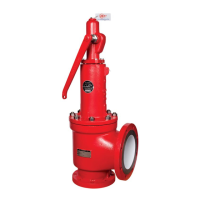
Lapping Procedure:
1. Use a cast iron lapping block or Pyrex lapping glass that is perfectly flat.
2. Select the appropriate compound from Table 1 and place a small
amount on the lap. When lapping the disc, use a light figure eight
motion (Figure 5). Frequently lift the disc away from the glass or block
to get a new bite on the compound.
3. Follow the same procedure when lapping nozzles or screwed valve
bodies except that the lapping block should be placed on the nozzle.
Use the same figure eight motion, frequently lifting the glass or block to
get a new bite on the compound.
4. Lap to a mirror finish. When done, make sure all compound is
completely removed from the parts using a suitable solvent. Handle the
parts with care to avoid scratching the seating surfaces.
Figure 5