C
Cheryl IbarraAug 17, 2025
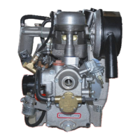
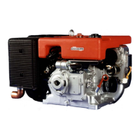
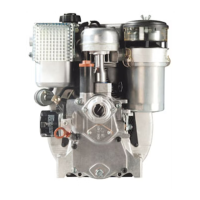
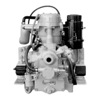
How to start Farymann Diesel Engine if it will not start?
- BBryan CareyAug 17, 2025
If the Farymann Diesel Engine won't start, it might be due to a fuel supply failure. Try filling it with fuel, no venting is needed. Also ensure the lever is set to full load.