H1 MANOEUVRES OF THE CRANE LOADS
(!) Before manoeuvering the load, verify that the working area is suitable
for your crane.
The lifting curves of the capacity plate indicate the maximum load that the crane
can lift at a certain radius and at a certain height. To utilize the maximum capa-
city of the crane, it is necessary to position the inner boom as indicated on the
capacity plate; the coloured symbols on the inner boom and column must coin-
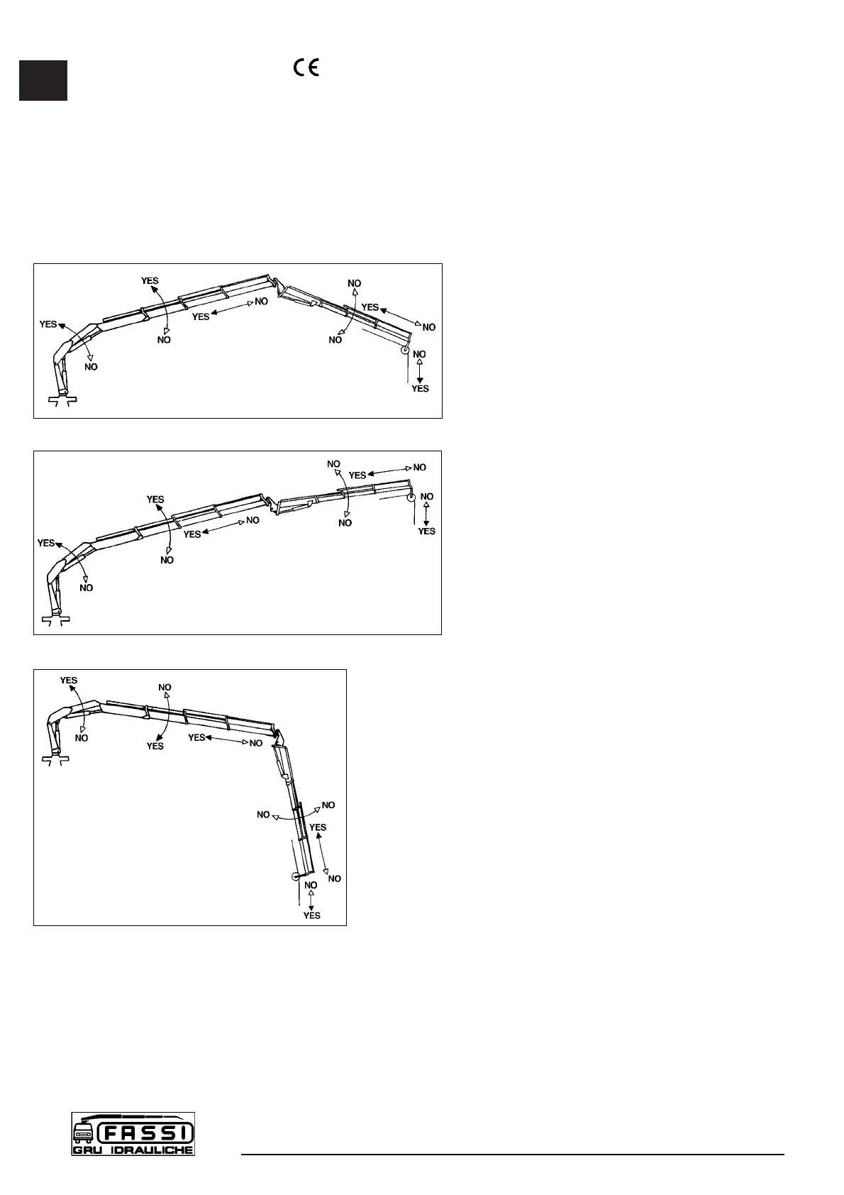
cide. During load handling, do not exceed the reach limits given, or the load
indicated on the above mentioned charts. If the limits are exceeded, the load
limiting device, allowing all manoeuvres, which
reduce the lifted load within the permitted reach
limits and forbid all other manoeuvres, will be
immediately activated.
Lifting moment limiting device
A characteristic which permits the classifica-
tion of cranes is their lifting capacity or maxi-
mum lifting moment. The moment is defined
by the value obtained from the weight of the
load to be lifted (kg) by its distance (meters)
from the centerline of the crane rotation.
The device called “lifting moment limiting device”
preserves the crane structure from overloads, as
it prevents any movement which increases the
value of the moment up to the maximum establi-
shed value.
H1.1 Lifting moment limiting device
“INTELLIGENT TYPE”
This device utilises an electrohydraulic tech-
nology, preventing any movement which causes an increase
in the pressure induced by the load in the inner and outer
rams of the crane (and of the hydraulic extension if fitted),
up to the “critical values”. These values, which are non-
exceedable, determine the intervention levels and provide
the data for setting the device.
The lifting moment limiting device concernes the following
manoeuvres:
- Inner boom descent; the inner boom lift is controlled
by the general main pressure valve of the distributor.
- Outer boom lift and descent.
- Extension of extension boom sections.
- Winch rope lift (if fitted).
- If hydraulic extension is fitted: extension outer boom
lift and descent.
- Extension of the jib extension booms section.
Crane with standard distributor
The lifting moment limiting device is based on hydraulic controls which are
activated when the intervention value is reached and block the movements of
the relevant distributor levers in one or both directions. Please remember that
the device will return the lever of the element being used to neutral position.
The condition of intervention is operated by the position of the outer boom (or,
if hydraulic extension is fitted, the position of the extension outer boom), on
which the electronic signal position (mercury level switch) is read by a special
electrovalve. This determines the controls of the locking or unlocking (reset-
ting) of the controls concerned.
H1
CONTROLS TO
OPERATE THE CRANE
F 170A
24
fig. 18a
fig. 18b
fig. 18c
 Loading...