www.fastech-motions.com - 17
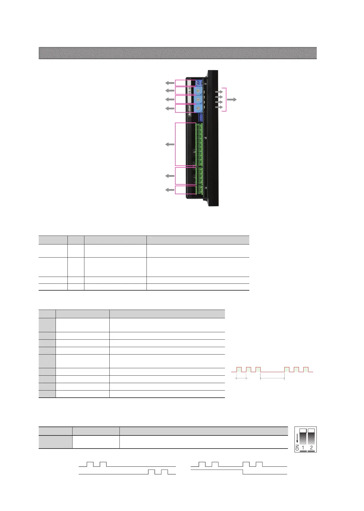
Drive status LED
Pulse input and direction setting switch(SW1)
Run current setting switch(SW2)
Resolution setting switch(SW3)
Stop current setting switch(SW4)
Input/Output singnal connection(CN3)
Motor connection(CN2)
Power connection(CN1)
15.1 Drive Status LED
◆ Protection functions and LED flash times
Indication Color Function ON/OFF Condition
POW Green Power input indication
Lights when power is ON Flashs when motor is
Free status
ALM Red Alarm indication
Flash when protection function is activated
(Identifiable which protection mode is activated
by counting the blinking times)
CW Yellow Motor Rotation Direction Lights when motor rotate CW direction
CCW Orange Motor Rotation Direction Lights when motor rotate CCW direction
Times Protection Conditions
1 Over Current Error
The current through power devices in drive exceeds
the limit value
*1
2 Over Speed Error Motor speed exceeded 3,000 [rpm]
3 Step Out Error Abnormally motor do not followed pulsed input
5 Over Temperature Error Internal temperature of a motor drive exceeded 85℃
6
Over Regenerative
Voltage Error
Back EMF more than 90V
7 Motor Connect Error Power is ON without connection of motor cable to drive
9 Motor Voltage Error Motor voltage is below 36V
11 System Error Error occurs in drive system
12 ROM Error Error occurs in Parameter storage Device(ROM)
15.2 Pulse Input Setting Switch(SW1.1)
Indication Switch Name Functions
2P/1P
Pulse input mode
Select Switch
Selectable 1-Pulse input mode or 2-Pulse input mode as Pulse input signal.
ON: 1-Pulse mode OFF: 2-Pulse mode ※ Default: 2-Pulse mode
CW(Pulse) Pin
CCW(Dir) Pin
Rotational Direction CW CWCCW CCW
2-Pulse Mode 1-Pulse Mode
Alarm LED flash
(Ex, Step Out Error)
2.0s0.5s
*1 : Limit value depends on motor model
15. Settings and Operation [Ezi-STEP-HPB series]