FB Series SIO Driver
GP-Pro EX Device/PLC Connection Manual
37
5 Cable Diagram
The cable diagram shown below may differ from that recommended by the
Fatek Automation Corporation
. Please
be assured, however, that there is no operational problem in applying the cable diagram shown in this manual.
• The FG pin on the External Device must be D-class grounded. Refer to your External Device manual for
details.
• The SG and FG are connected inside the Display. If you connect the External Device to the SG, do not form
any short-circuit loop in the system design.
• If the communication is not stable because of noise or other factors, connect an isolation unit.
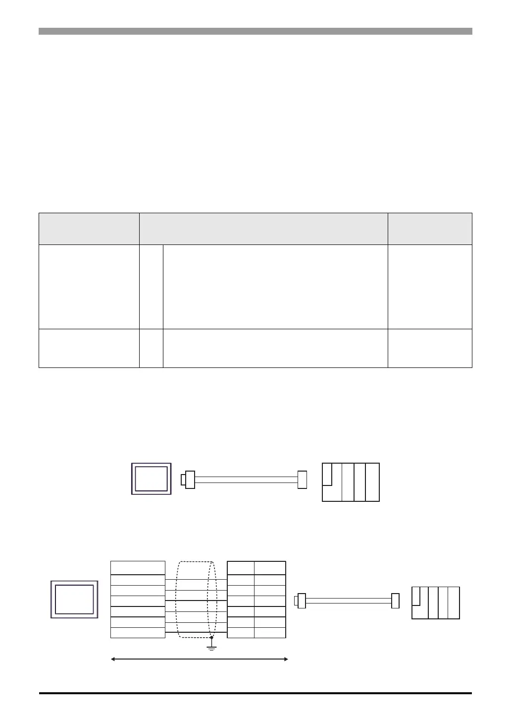
Cable Diagram 1
1A)
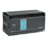
1B)
Display
(Connection Port)
Cable Remarks
GP3000 (COM1)
GP4000
*1
(COM1)
SP5000 (COM1/2)
ST (COM1)
LT3000 (COM1)
IPC
*2
PC/AT
*1 All GP4000 models except GP-4100 Series and GP-4203T
*2 Available only with a COM port that supports RS232C.
) IPC COM Port (page 6)
1A FBs-232P0-9F-150 by Fatek Automation Corporation -
GP-4105 (COM1) 1B
User-created Cable
+
FBs-232P0-9F-150 by Fatek Automation Corporation
Cable length:
15m or less
Display
FBs-232P0-9F-150
External Device
Mini DIN(plug)
FBs-232P0-9F-150
External Device
Mini DIN(plug)
Display
Display side
Terminal block
Signal
name
RD(RXD)
SD(TXD)
ER(DTR)
SG
RS(RTS)
CS(CTS)
External Device side
D-sub 9 pin (plug)
Pin
2
3
4
5
7
8
RD(RXD)
SD(TXD)
ER(DTR)
SG
RS(RTS)
CS(CTS)
Shield
Signal
name
User-created cable