50
4. Connection
SD3 Series Instruction Manual
5. Descriptions of CN1 Connector Signals
RS
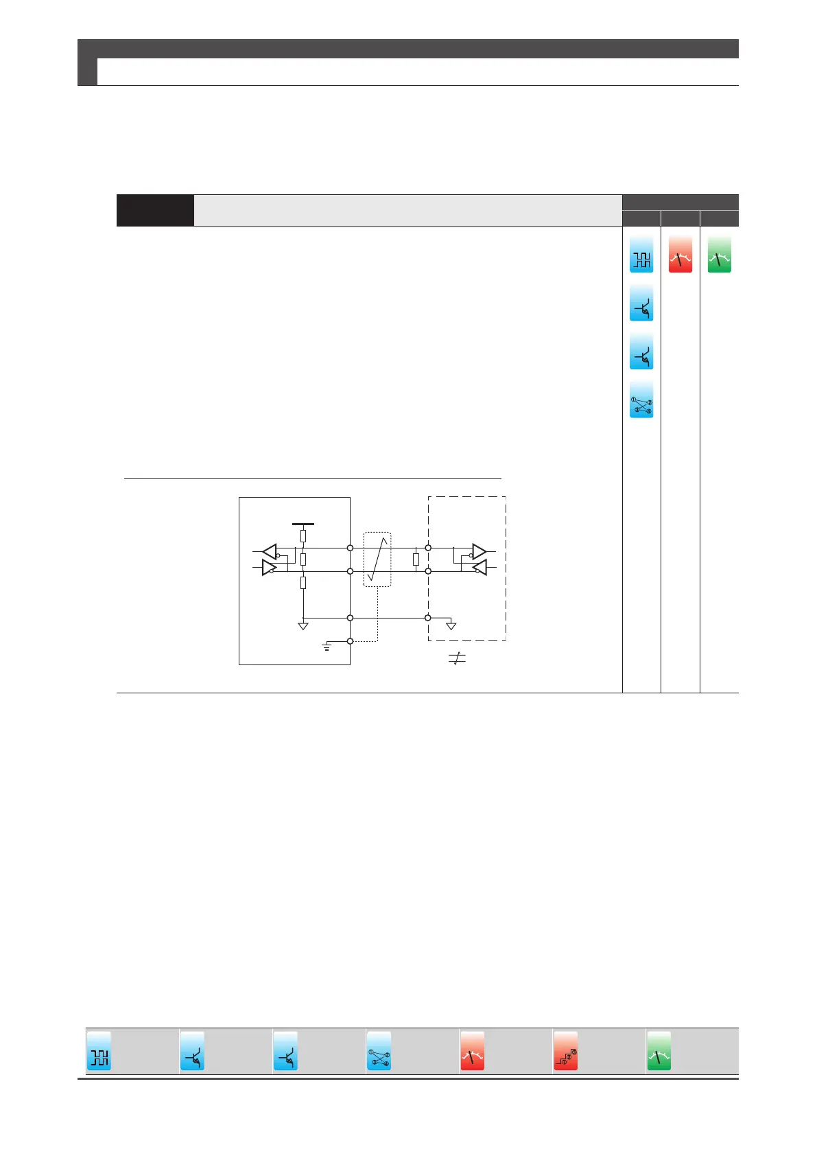
Connection to RS-485 circuit
Control Mode
P V T
RS-485 communications with the host controller
When connecting multiple ampliers, be sure to install a termination resistor of
approximately 200 Ω between signal lines of the end amplier.
Be sure to connect a pull-up resistor (RPU) and a pull-down resistor (RPD) of approximately
1.2 k Ω inside the host controller. Be sure to connect a termination resistor of approximately
220 Ω .
Make the wiring between the host controller and the amplier less than 3 m.
Between ampliers, make it less than 1 m.
Signal ground of communication IC of the amplier is connected to signal ground inside the
amplier. Connect signal ground of communications IC of the host controller to Pin No.45.
Be sure to use shielded twisted-pair cable as a noise countermeasure.
SG
5 V
RPU
RT
RPD
43
(485)
44
(/485)
SG
45
(SG)
FG
RT
Shield
Twisted-paircable
Amplifier
䐟
䐠
䐡
䐢
ol
ol
Dierential
24 V
open collector
5 V
open collector
䐟
䐡
䐢
Internal
Position
ol
Analog
Velocity
䐟
䐠
Internal
Velocity
ol
Analog
Torque
 Loading...