7. OPERATION OF THE DISPENSER
7.1 OPERATING ELECTRONIC CONTROLS
A. The electronic machine controls are designed to provide a logical sequence of operation with a
minimum of written instruction. System operating parameters are selected and set from a
menu.
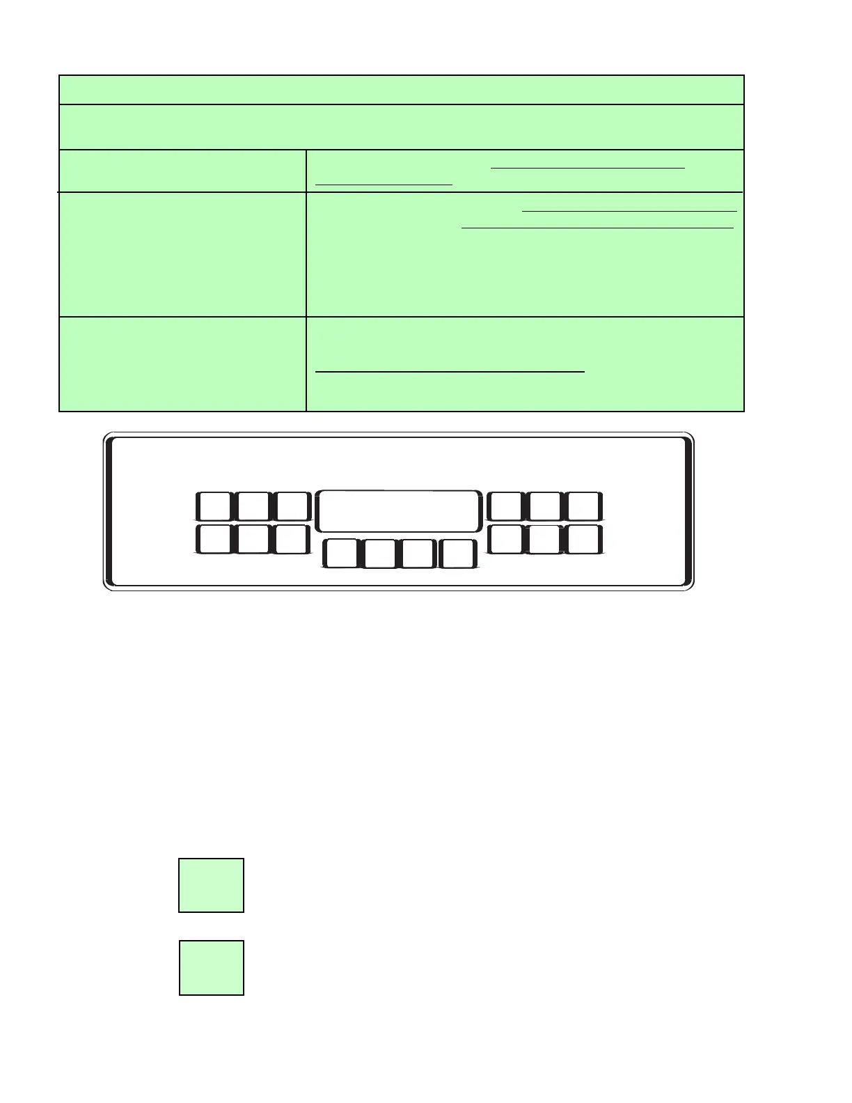
B. LEFT and RIGHT Side Buttons (see Figure 7.1).
1. Each side has five (5) active buttons. They are labeled FILL, BEATER, RUN, DEF (defrost),
and OFF.
2. Each button operates a double acting switch. Pressing the button once activates the
process. Pressing the button a second time deactivates the process. Take care not to
double press the buttons when first activating a process.
The RUN button initiates the freeze process. After pressing this button, the
beater motors will run for two minutes before the compressor starts. This
delay eliminates the possibility of "short cycle" damage to the compressor.
Run also maintains the flow of product into the chambers when needed.
The OFF button turns off all the machine's refrigeration and chamber refill
systems. All of the electronic controls are still active.
CRITICAL REGULATOR AND FLOW CONTROL SETTINGS
SET ALL PRESSURES USING THE LCD READOUTS ON THE UNIT - NOT BY THE GAUGES ON THE
REGULATORS!
CO
2 PRIMARY REGULATOR The CO2 Primary Regulator MUST BE SET TO 70-72 PSIG
(482.6 TO 496.4 KPa).
CO
2 SECONDARY REGULATOR The CO2 Secondary Regulator SHOULD BE SET AT 28-32 PSI
(Secondary Regulator) (206.8 TO 220.8 KPa) STATIC PRESSURE.
The CO2 Secondary Regulator is on the header assembly which is
behind the access panel. This regulator is a “non-vent” regulator.
This means that if you lower the regulator setting, you will need to
dispense drinks (with “Fill” activated) until cylinder begins to refill
before the new setting will register on the gauge.
FLOW CONTROLLERS WATER FLOW MUST BE SET TO PROVIDE A FLOW OF
15 OUNCES IN 10 SECONDS BEFORE ADJUSTING THE BRIX.
BRIX MUST
BE SET BETWEEN 13.5 - 15. Flow controllers are on
the header assembly. A sample may be taken by fully depressing the
sample valve while”FILL” is in the “OFF” position.
7
OFF
RUN
FILL
BEATER
RUN
DEF.
OFF
FILL BEATER RUN
OFF
DEF.
BACK FWD SELECTCANCEL
LEFT SIDE RIGHT SIDE
FBD
Figure 7.1