Do you have a question about the FBII XL-31 and is the answer not in the manual?
Illustrates the physical wiring connections for the control panel, power sources, and system zones.
Details specific terminal assignments for power, zones, keypads, and communication interfaces.
Provides step-by-step instructions for securely mounting the main circuit board within the control panel enclosure.
Details grounding lug connection, zone information, keypad connection requirements, and addressing protocols.
Explains telephone line connectivity, trigger outputs, and backup battery installation.
Details mounting procedures for the XL4612RM keypad using double gang boxes or mounting rings.
Explains surface mounting methods for the XL4612SM keypad to control panels, junction boxes, or walls.
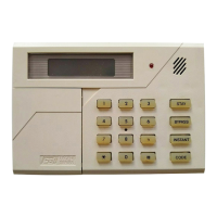
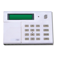
Covers surface and recessed mounting instructions for the 7005 and 7015 keypad models.
Explains the system's power-up sequence and reset behavior.
Details how to arm the system, including fail-safe arming and exit delay.
Explains the STAY arming mode and keypad responses.
Explains the INSTANT arming mode and keypad responses.
Explains the INSTANT-STAY arming mode and keypad responses.
Explains how to disarm the system and clear alarm memory.
Explains how to reset the system, silence alarms, and clear displays.
Explains how to bypass zones, rules, and options.
Explains automatic unbypassing of zones.
Explains how to manually unbypass zones.
Details how to program user codes, types, and applications.
Explains the procedure for removing user codes from the system.
Describes the four separate keypad auxiliary conditions and their keystrokes.
Introduces the programming questions section, defining parameters for system configuration.
Defines dialer format options for transmitting alarm signals to the central station.
Specifies receiver types compatible with various transmission protocols for central station monitoring.
Configures pulse types, dialer disable, and split reporting options for communication.
Sets system options related to zone 12 response, swinger shutdown, and restore behavior.
Configures keypad emergency conditions like panic, auxiliary, and reset functions.
Defines phone line failure detection time and associated alarm responses.
Configures quick commands, arm-only user, and door strike trigger activation.
Sets the interval for central station test transmissions.
Configures miscellaneous system options including siren output, auto-arming, and user code requirements.
Sets ring count for pickup, bypass on stay, and bell test at arming options.
Enter the subscriber account number for the primary central station receiver.
Enter the subscriber account number for the secondary central station receiver.
Specifies zone supervision methods like EOL or Normally Open/Closed.
Selects zone types for burglary or 24-hour applications, including fire and trouble.
Provides detailed descriptions of burglary and 24-hour zone types, including their behavior.
Describes the 24-hour trouble zone type, its active status, and bypass limitations.
Explains keyswitch zone operation and its compatibility with Underwriters Laboratories.
Details how to program alarm codes for central station reporting based on dialer format.
Maps PID event codes to specific alarm, trouble, and system events for reporting.
Defines the zone number transmitted to the central station for reporting purposes.
Details the keystrokes required to enter the system's programming mode.
Describes how to interpret the display and LED indicators during programming operations.
Explains the process of entering data, moving between questions, and saving entries.
Details the keystrokes required to enter the system's programming mode via LCD keypads.
Describes the display format for question number, location, and data during LCD keypad programming.
Explains data entry methods, movement between questions, and saving information on LCD keypads.
| Brand | FBII |
|---|---|
| Model | XL-31 |
| Category | Security System |
| Language | English |