EasyManua.ls Logo

FBII OMNI-600 EU - User Manual

FBII OMNI-600 EU
96 pages
Print Icon
To Next Page IconTo Next Page
Loading...
6HF XULW\6\VWHP
2
2
0
0
1
1
,
,
2
2
0
0
1
1
,
,
(
(
8
8
2
2
0
0
1
1
,
,
2
2
0
0
1
1
,
,
(
(
8
8
,QVWDOODWLRQDQG6HWXS*XLGH
ARMED
READY
1
4
7
2
5
8
0
3
6
9
#
STAY
BYPASS
INSTANT
CODE
ARMED
READY
1
4
7
2
5
8
0
3
6
9
#
STAY
BYPASS
INSTANT
CODE
1 3
2
4 6
5
7 9
8
#
0
STAY INSTANT
BYPASS
CODE
ARM
AC / LB
READY
STAY
INST
LO BATT
SPRV.
N9979 5/01

Table of Contents

Questions and Answers

  • S
    sean32Aug 7, 2025
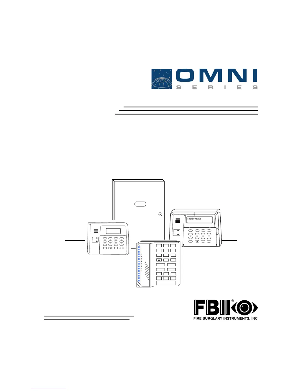
    What to do if the ARM light is slowly blinking and the LCD KP shows COMM FAILURE on my FBII Security System?
    • A
      Amber WallaceAug 7, 2025
      If the ARM light is slowly blinking and the LCD KP displays 'COMM FAILURE', it indicates a failure to communicate with the central station. First, check for any cut or disconnected telephone lines and repair them if needed. Then, verify the panel programming for any incorrect central station information and reprogram it with the correct details if necessary. If the issue persists, it might be due to faulty telephone lines, in which case you should consult your local telephone company. As a last resort, the panel itself might be faulty and need replacement.
  • A
    angelawalkerAug 12, 2025
    Why is the AC/LB light OFF on my FBII OMNI-600 EU Security System?
    • T
      Tonya MillsAug 12, 2025
      If the AC/LB light is off, it could be due to a primary AC power outage. Check the transformer connection and the AC input voltage. Alternatively, the keypad might be faulty, requiring replacement.
  • Q
    qrogersAug 16, 2025
    What to do if the Siren/Speaker does not sound in my FBII Security System?
    • H
      Hunter DunnAug 16, 2025
      If the siren or speaker isn't working, first test the siren/speaker by connecting it directly to a 12VDC power source. If no sound is produced, replace the siren/speaker. Next, inspect the wiring for any open or short circuits, and replace the wiring if necessary. Finally, check terminals 3 (+) and 4 (-) for 12VDC when the panel is in alarm (if programmed for bell output); if no voltage is measured, the panel might be faulty and need replacement.
  • V
    Veronica JonesAug 22, 2025
    How to fix ZONE light ON & READY light OFF issue in FBII Security System?
    • G
      gmichaelAug 22, 2025
      If the ZONE light is ON and the READY light is OFF, it means a zone is faulted and the system isn't ready. Inspect the loop wiring for any opens or shorts and repair them. Also, check the EOL resistor for any opens or incorrect values. Another possible cause is a faulty keypad that needs to be replaced. As a final check, verify the zone terminal voltage for 3.3VDC; you can also temporarily bypass the zone to test; if the problem persists, replace the panel.
  • M
    Mark HarrisAug 27, 2025
    How to troubleshoot AC/LB light slowly blinking with LCD KP showing LOW BAT on FBII Security System?
    • D
      duncanmichaelAug 27, 2025
      If the AC/LB light is slowly blinking and the LCD KP displays 'LOW BAT', it indicates a DC power issue or low battery voltage. Check the battery connections and the battery voltage with the transformer disconnected. If the voltage is less than 11VDC, let the battery charge or replace it.
  • T
    Timothy TownsendSep 1, 2025
    How to fix a keypad display that is not lit on my FBII OMNI-600 EU?
    • R
      rdoughertySep 1, 2025
      If the keypad display is not lit, it could be due to a loss of both AC and DC power. Check the transformer and battery connections, and verify the AC input and battery voltage with the transformer disconnected. Another potential cause is that the keypad isn't receiving power. In this case, check terminals 20 (+) and 17 (-) for 12VDC.

Summary

OMNI Security System Overview

OMNI System Features

Details the features of the OMNI-400, OMNI-400EU, OMNI-600, and OMNI-600EU control panels.

SECTION 2 System Wiring and Hookup

OMNI System Wiring Diagram

Illustrates the electrical connections for the OMNI security system, including terminals and devices.

Control Panel Terminal Connections

Details the function and connection of each terminal on the control panel for power, bell, and other devices.

SECTION 3 PC Board and Keypad Mounting

PC Board Mounting Instructions

Step-by-step instructions for mounting the main circuit board into the control panel cabinet.

SECTION 4 System Configuration

System Hardwire Zone Configuration

Explains programming options for hardwired zones, including standard, double-balanced, and zone doubling configurations.

SECTION 5 System Operation

Supported Keypads and Functions

Introduces the types of keypads supported by the control panel and their basic functions.

System Arming Procedures

Instructions on how to arm the system in different modes (Away, Stay, Instant) and keypad indications.

Stay and Instant Arming Modes

Details how to arm the system in the combined Stay/Instant mode and keypad indications.

System Disarming, Reset, and Alarm Memory

Explains disarming, handling alarm memory, and system reset.

User Code Programming and Management

Details how to program, modify, or delete user codes and their authority levels.

Quick Arming and System Status Display

Explains quick arming functions and how to view system status like zone directory and time.

Quick Forced Arming and System Time Setting

Explains quick forced arming and setting the system's time and date.

SECTION 6 System Programming

System Programming Methods and Defaults

Details programming methods (keypad, PC) and how to reset system defaults.

Keypad Programming Display Differences

Explains programming differences for LED and fixed-word keypads compared to LCD keypads.

Installer Mode Functions Summary

Provides a summary of the nine installer modes for system configuration and maintenance.

Installer Mode 1: Keypad Programming Details

Details the submodes for installer keypad programming and navigation.

Installer Mode 9: On-Line Download Procedure

Explains how installers initiate remote communications sessions for programming and updates.

Summary of System Programming

Installer Mode 1: Programming Questions Overview

Defines programming questions and values for Installer Mode 1: System Options.

Telephone and Pager Number Programming

Details programming of telephone and pager numbers for central station communication.

CS Dialer Format and Receiver Type Configuration

Specifies dialer format and receiver type for central station reporting.

Central Station Reporting Options

Defines reporting options like backup, dual, split reporting, and dialer disable.

QUESTION 11 ARMING OPTIONS

System Arming Options Configuration

Defines arming options including auto-arm, instant arming, and stay arming.

QUESTION 14 LOG OPTIONS

QUESTION 16 ENTRY-EXIT DELAY;DIALER DELAY

QUESTION 18 SOFT KEY FUNCTIONS

QUESTION 20 AUTO-ARM;KEYPAD TAMPER ENABLES

Auto-Arm and Keypad Tamper Enable Settings

Enables auto-arming and keypad tamper reporting functions.

QUESTION 21 AUTO-ARM TIME

QUESTIONS 23-29 TRIGGER;RELAY TYPES

Programming Submode 2: ZONE PROGRAMMING; REPORT CODES

Zone Types and Attributes Configuration

Defines zone types and attributes, including instant, delay, interior, and 24-hour zone configurations.

QUESTIONS 13-18 ZONE REPORT CODES

QUESTIONS 33-35 CROSSED ZONES

Programming Submode 4: DESCRIPTOR PROGRAMMING

SECTION 7 Summary of Keypad Functions

User Functions Overview

Summarizes common user functions accessible via keypad: arming, bypassing, code management, and more.

Installer Mode Functions Overview

Lists and describes the various installer modes for system configuration and maintenance.

SECTION 8 Central Station Reporting Formats

ADEMCO 4 x2 Express and Point ID Formats

Details ADEMCO 4x2 Express and Point ID formats for advanced reporting with PID codes.

SECTION 9 Troubleshooting

FBII OMNI-600 EU Specifications

General IconGeneral
BrandFBII
ModelOMNI-600 EU
CategorySecurity System
LanguageEnglish

Related product manuals