FLT93 Flow Switch Series FLUID COMPONENTS INTERNATIONAL LLC
Doc. No. 06EN003312 Rev. D 5
This page is subject to proprietary rights statement on last page
Alarm Adjustment Procedure
(Not necessary if the instrument has been factory calibrated.)
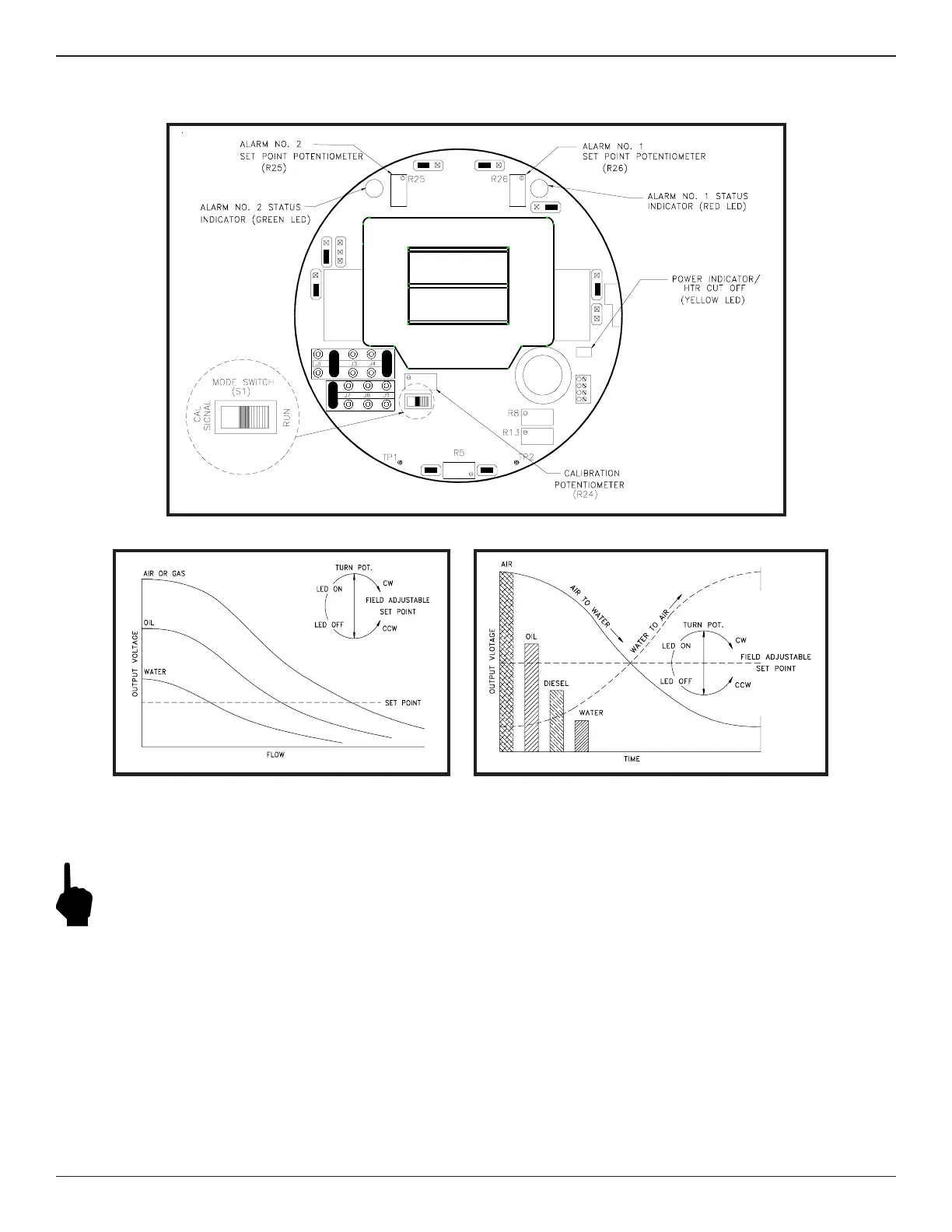
Control Circuit Adjustment Locations
Flow Application Signal Output
Level Application Signal Output
Adjustment by Observation (Option 1)
Note:
The control circuit has two mutually exclusive alarms; they are identified as Alarm No. 1 and Alarm No. 2 and
each has a set point adjustment potentiometer and LED indicator. Each alarm can be setup for one of three
applications: flow, level/interface, or temperature. The following application specific adjustment procedures
are generic and can be used for setting either or both alarms. The mode switch must be in the RUN position.
Use the top figure on this page to help locate the adjustment potentiometers and LEDs.
Flow Applications
1. Ensure that the instrument has been properly installed in the pipeline. Fill the pipeline so the sensing element is
surrounded by the process media.
2. Apply power to the instrument and allow fifteen minutes for the sensing element to become active and stabilize.
3. Flow the pipeline at the normal or expected rate. Remove the enclosure cover to allow access to the control circuit
to make adjustments.
 Loading...


