MSS
TM
Series
© Copyright 2022 Fluid Equipment Development Company | www.fedco-usa.com
- 34 -
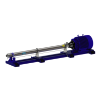
Figure 67 - Discharge Housing Alignment Pin
6. Locate the discharge housing anti-rotation
pin on the bearing carrier and note the loca-
tion of the discharge housing anti-rotation
pin hole.
Figure 66 - Installing Cavity Cover
5. Lubricate the cavity cover O-ring and install
the cavity cover.
NOTES: Make sure to align throttle nipple
opening with the bottom of the pump.
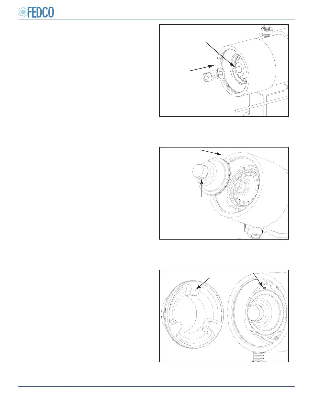
Figure 65 - Installing Balance Disc Washers
and Nut
APPLY SYSTEM COMPLIANT
ANTI-SEIZE COMPOUND
4. Apply system compliant anti-seize com-
pound onto the pump shaft threads and
install the balance disc washer, lock washer
and shaft nut. Tighten to torque value speci-
ed in the Fastener Torque Specications
section of this manual.
NOTES: The pump shaft nut preload is critical
to proper balance disc operation. A properly
calibrated torque wrench must be used for this
step.
Pump Overhaul Continued