MSS
TM
Series
© Copyright 2022 Fluid Equipment Development Company | www.fedco-usa.com
- 35 -
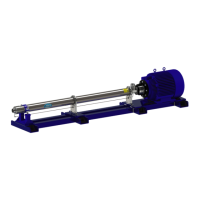
Figure 70 - Install Discharge Housing Retaining
Clips
10. Install the retention clips, lock washers and
cap screws. Tighten to torque value speci-
ed in the Fastener Torque Specications
section of this manual.
Figure 69 - Inspecting Discharge Housing
Alignment
8. Temporarily install the throttle nipple to
ensure the cavity cover and the discharge
housing are properly aligned.
9. Remove the throttle nipple.
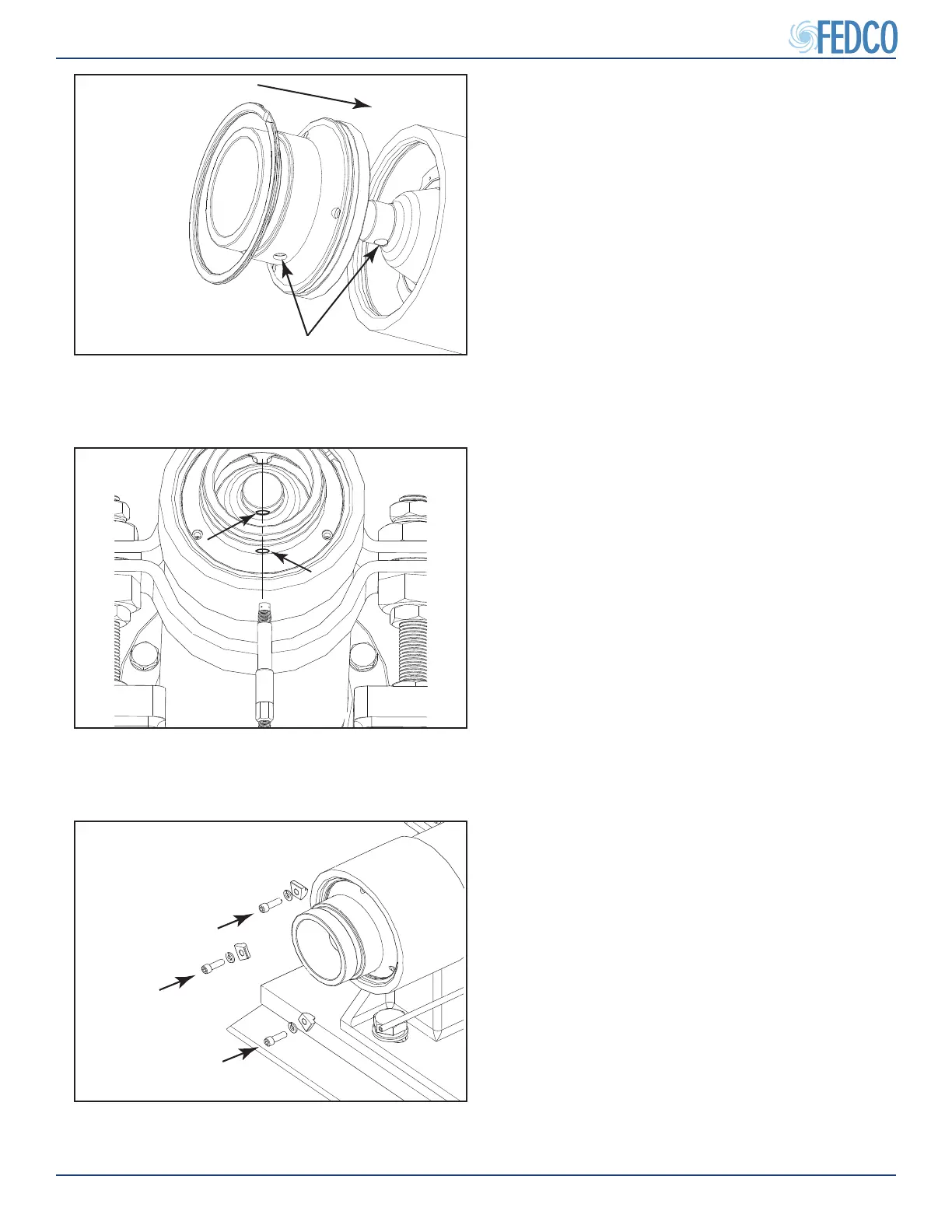
Figure 68 - Installing Discharge Housing
7. Lubricate the discharge housing O-ring and
install the discharge housing and retaining
ring.
NOTES: Make sure to align the throttle nipple
opening in the discharge housing with the
throttle nipple opening in cavity cover.
Pump Overhaul Continued