MSS
TM
Series
© Copyright 2022 Fluid Equipment Development Company | www.fedco-usa.com
- 41 -
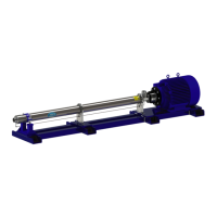
Figure 86 - End Shell Bolt Removal
Stage Removal
1. For:
Single Shell Pumps:
Remove the end shell ange bolts from the
inlet ange and safely remove end shell
using safe lifting and handling methods.
Remove the inlet O-ring.
Two Shell Pumps:
Remove the end shell ange bolts from the
series shell ange and safely remove end
shell using safe lifting and handling meth-
ods. Remove the series shell O-ring.
NOTES: The MSS-50/70 models have the last
diuser housing welded within the shell(s) and
cannot be removed individually. These are
considered part of the shell assembly and will
come out when shell is removed.
Figure 85 - Balance Disc Removal
15. Proceed by preforming the Balance Disc
Removal procedure as described earlier in
this manual.
NOTES: Although pump is orientated vertically,
the balance disc removal procedure is identi-
cal to horizontal procedure. Skip the drain line
removal steps as this is already completed.
NOTES: Inspect the surfaces of the balance
disc for unusual wear. See the Balance Disc
Wear Chart section of this manual for addition-
al information.
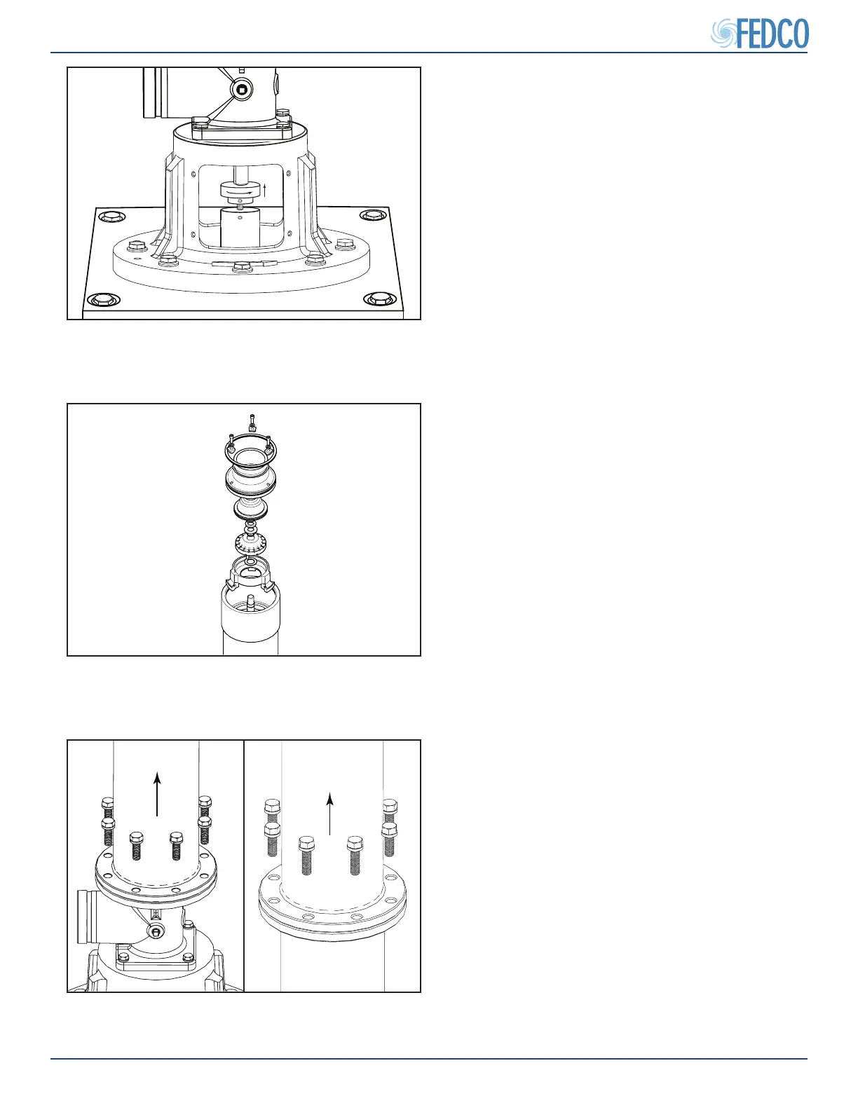
Figure 84 - Setting the Gauge Block
14. With the pump secured in the vertical posi-
tion, install and adjust an adjustable gauge
block in the center of the motor adapter until
it comes into contact with the bottom of the
pump shaft.
NOTES: Install shaft locking wrench at this
time.
Pump Overhaul Continued