MSS
TM
Series
© Copyright 2022 Fluid Equipment Development Company | www.fedco-usa.com
- 42 -
Figure 89 - Series Shell Removal
5. For:
Single Shell Pumps:
Skip this step.
Two Shell Pumps:
When all stages in pump end shell section
have been removed, proceed by removing
the series shell ange bolts from the inlet
ange and safely remove using safe lifting
and handling methods. Remove the series
spacer. Continue stage component removal
(previous step).
NOTES: The MSS-50/70 models have the last
diuser housing welded within the shell(s) and
cannot be removed individually. These are
considered part of the shell assembly and will
come out when shell is removed.
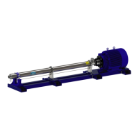
Figure 88 - Stage Removal
4. Remove all stage components: diusers,
impellers, and stage spacers.
NOTES: MSS-50/70 stage components may
dier in size/ shape.
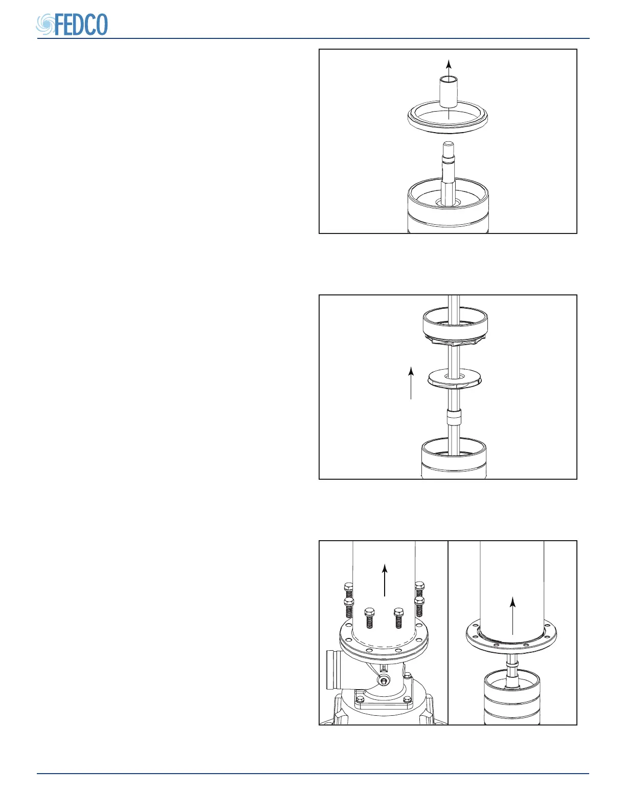
Figure 87 - Discharge Ring Removal
2. Remove the discharge ring
3. Remove the end spacer.
NOTES: The end spacer is dimensionally dif-
ferent from the stage spacers and needs to be
kept separately. On some installations, this end
spacer may be engraved to help distinguish it
from standard stock spacers.
NOTES: The discharge ring in the MSS-50/70
models is welded within the shell and cannot
be removed individually. The discharge ring is
considered part of the shell assembly.
Pump Overhaul Continued