MSS
TM
Series
© Copyright 2022 Fluid Equipment Development Company | www.fedco-usa.com
- 43 -
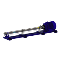
Figure 92 - Shaft Collar Installation
Stage Installation
NOTES: Continue supporting the weight of the
shaft to avoid damage to the mechanical seal.
1. Remove, inspect, and replace the shaft if
necessary.
a. Place the collar sleeve and the retaining
ring onto the pump shaft. Make sure the
collar sleeve’s cup side is facing towards
the motor coupling shaft end.
b. Place the split collar halves onto the pump
shaft and slide the collar sleeve over the
split collar halves.
c. Install the retaining ring into the split collar
sleeve.
d. Install the mechanical seal retaining ring
onto the pump shaft.
NOTES: Only remove pump shaft/ mechanical
seal if necessary.
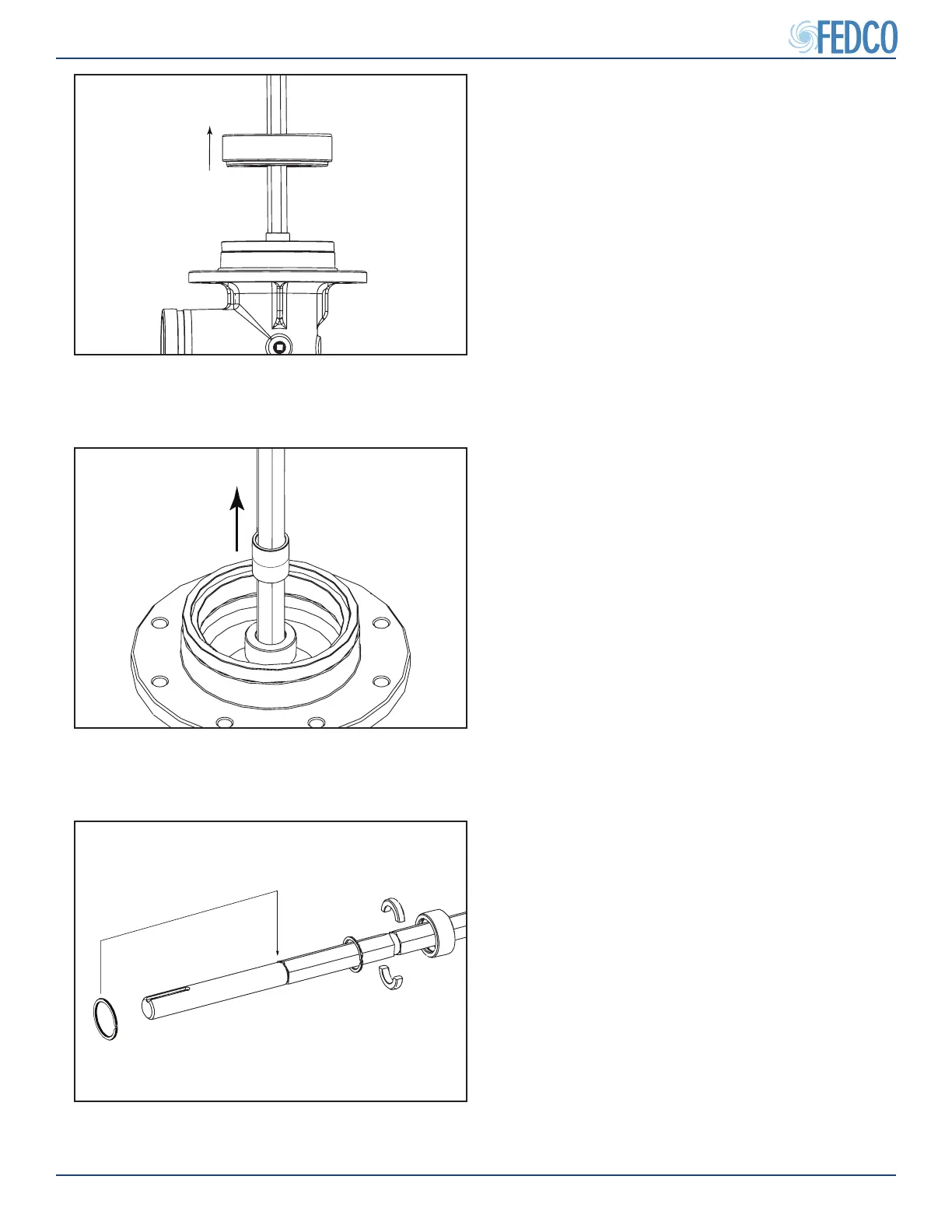
Figure 91 - First Stage Spacer Removal
7. Inspect the inlet ring for excessive wear.
NOTES: Remove the inlet ring and replace if
necessary. The inlet/ discharge rings are not
included in any eld service kits but can be pur-
chased separately.
8. Remove the rst stage (start) spacer.
NOTES: The rst stage spacer may be dimen-
sionally dierent from the stage spacers and
needs to be kept separately. On some installa-
tions, this start spacer may be engraved to help
distinguish it from standard stock spacers.
Figure 90 - Starting Stage Removal
6. Remove the rst stage housing (diuser
bowl).
NOTES: The rst stage housing (diuser) can
be identied by the lack of vanes on the bottom
of the bowl. Because this component is dier-
ent than the other diusers it should be kept in
a separate location.
NOTES: The shaft will no longer be supported
by stages and will fall over or cause damage to
the bushing and seal if not supported.
Pump Overhaul Continued