MSS
TM
Series
© Copyright 2022 Fluid Equipment Development Company | www.fedco-usa.com
- 44 -
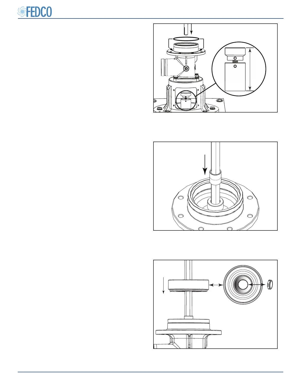
Figure 95 - Starting Stage Installation
4. For:
MSS-15/20/30 Pumps:
Install the rst stage housing (diuser bowl)
onto the inlet ring. Note that the rst stage
housing (diuser) can be identied by the
lack of vanes on the bottom of the bowl.
MSS-50/70 Pumps:
Install the rst diuser bowl onto the inlet
ring.
NOTES: Verify diuser bushings have been
pre-installed before assembly.
Figure 94 - First Stage Spacer Installation
3. Install the rst stage (start) spacer onto the
pump shaft until it comes into contact with
the shaft collar sleeve.
NOTES: The start spacer must contact the col-
lar sleeve as shown. If the collar sleeve’s cup
side if facing up, it is on upside down.
NOTES: The rst stage spacer is dimension-
ally dierent from the stage spacers. On some
installations, this start spacer may be engraved
to help distinguish it from standard stock spac-
ers.
NOTES: MSS-50/70 stage components may
dier in size/ shape.
Figure 93 - Shaft Installation
e. Slowly lower the pump shaft into the inlet
until the pump shaft end rests on the gage
block.
2. Lubricate and install the inlet O-ring.
NOTES: Gauge block height should be preset
from the stage removal section. Verify height
before building. Contact FEDCO eld service
for gauge block height if unknown. The pump
serial number must be provided.
Pump Overhaul Continued