MSS
TM
Series
© Copyright 2022 Fluid Equipment Development Company | www.fedco-usa.com
- 52 -
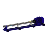
Figure 115 - Impeller Assembly
Anti-Seize
3. Apply anti-seize compound to the split cone
threads
4. Install the split cone into the impeller
5. Loosely install the split cone nut onto the
split cone
Figure 114 - Floating/ Clamping Neck Ring
Installation
2. Install a oating neck ring and clamping neck
ring from into the inlet ring.
Pump Overhaul Continued
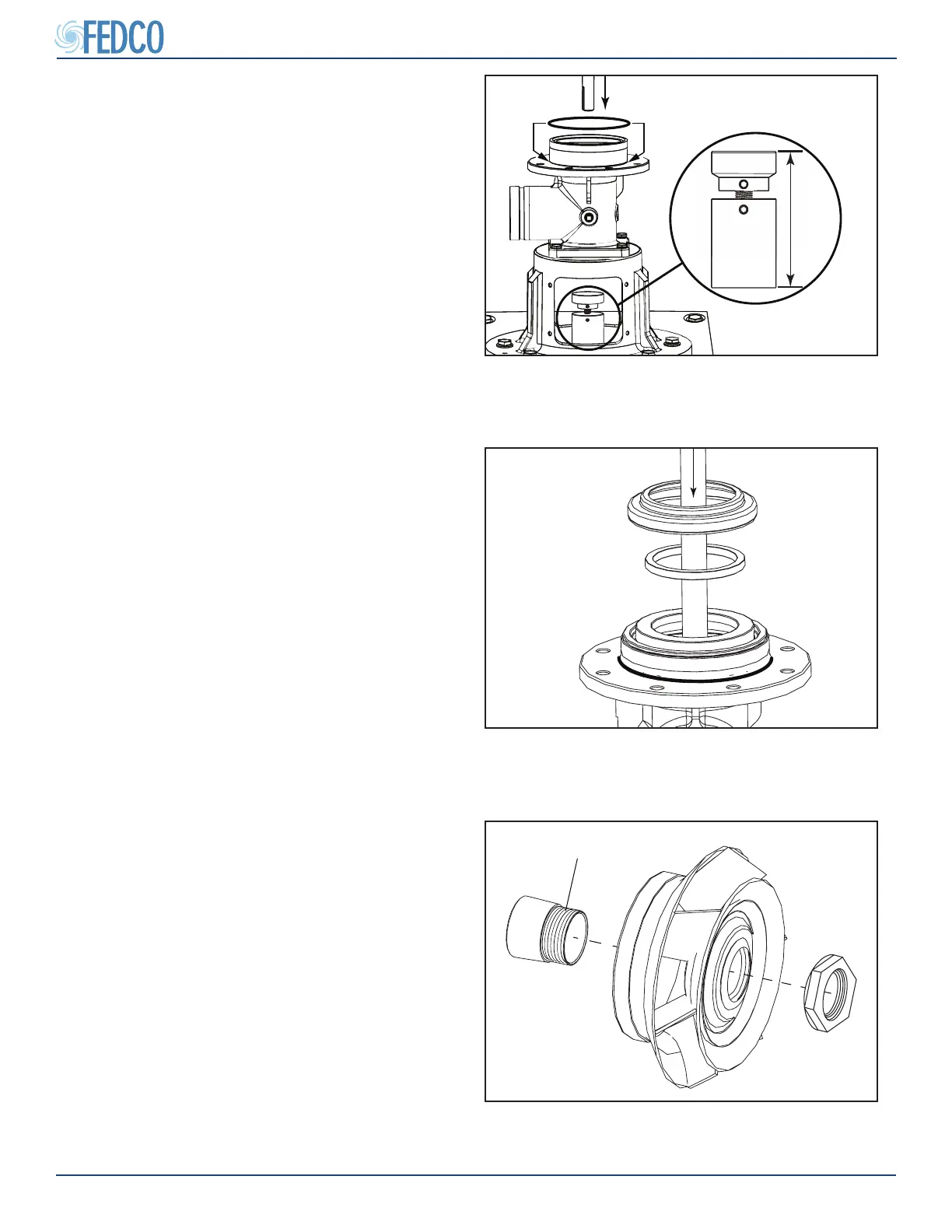
Figure 116 - Shaft Installation
b. Slowly lower the pump shaft into the inlet
until the pump shaft end rests on the gage
block.
6. Lubricate and install the inlet O-ring.
NOTES: Gauge block height should be preset
from the stage removal section. Verify height
before building. Contact FEDCO eld service
for gauge block height if unknown. The pump
serial number must be provided.