MSS
TM
Series
© Copyright 2022 Fluid Equipment Development Company | www.fedco-usa.com
- 53 -
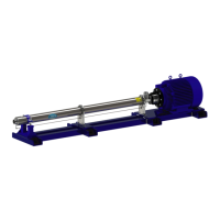
Figure 119 - Impeller Installation
13. Adjust the impeller height so that the seam
on the impeller ring is level with the top of
the oating neck ring.
14. Using a suitable tool, gently pry upwards on
the split cone nut and draw the split cone up
into the impeller before tightening.
15. Grasp impeller to prevent rotation and
tighten split cone nut to torque value speci-
ed in the Fastener Torque Specications
section of this manual.
Figure 118 - Diuser Installation
10. Place two (2) spacer washers approximate-
ly 2.8mm (0.11”) thick between the inlet ring
and diuser.
11. Install a fully assembled diuser (diuser,
diuser bearing, oating neck ring, and
clamping neck ring) onto the pump shaft
and seat the diuser assembly onto the
spacer washers.
12. Repeat the impeller assembly procedure
and slide assembly onto pump shaft.
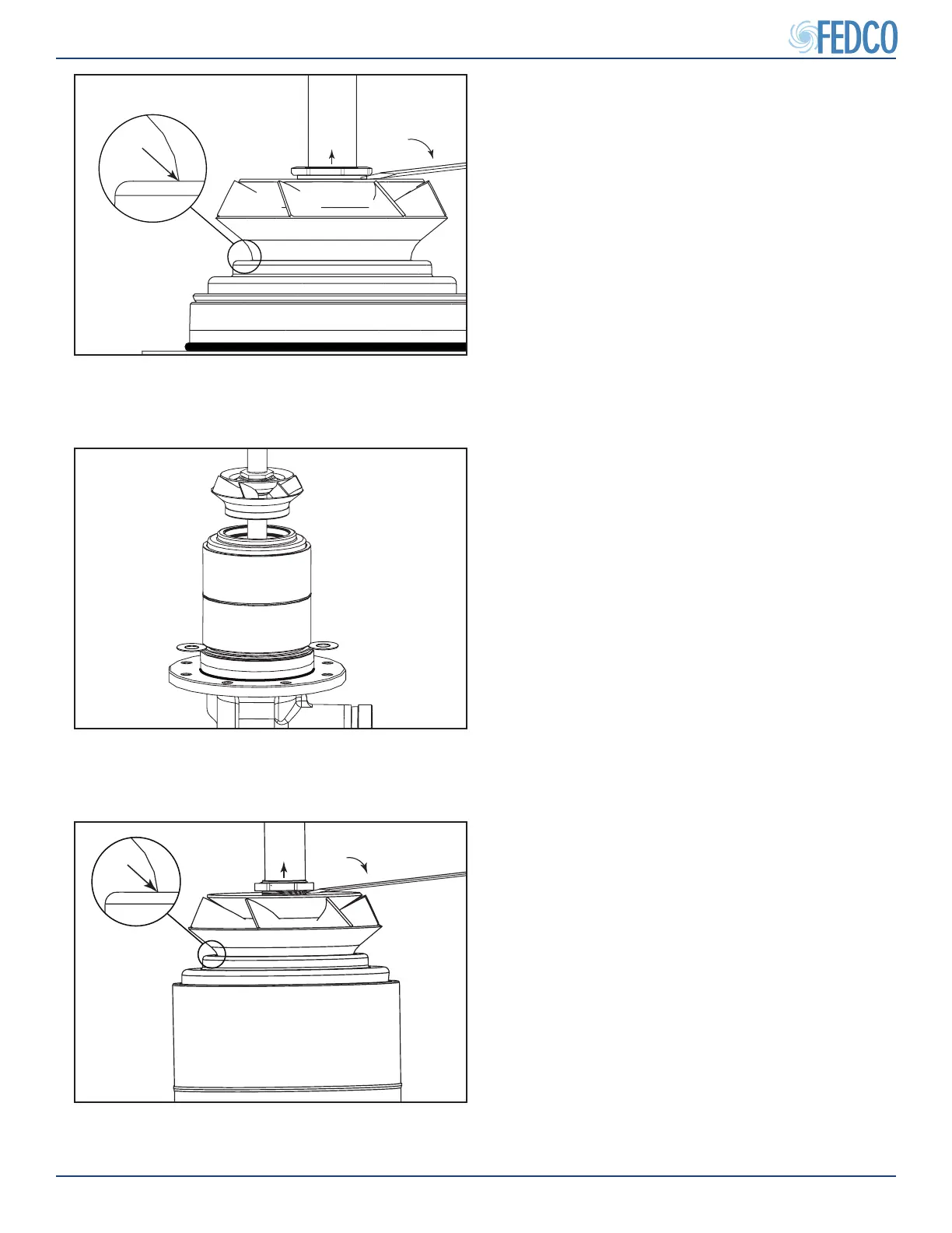
Figure 117 - Impeller Installation
Impeller ring seam and
top of oating neck ring
7. Slide the impeller assembly over the pump
shaft and adjust the impeller height so that
the seam on the impeller ring is level with
the top of the oating neck ring.
8. Using a suitable tool, gently pry upwards on
the split cone nut and draw the split cone up
into the impeller before tightening.
9. Grasp impeller to prevent rotation and tight-
en split cone nut to torque value specied in
the Fastener Torque Specications section
of this manual.
Pump Overhaul Continued