MSS
TM
Series
© Copyright 2022 Fluid Equipment Development Company | www.fedco-usa.com
- 56 -
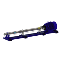
Figure 128 - Lowering Unit Into Mounting
Position
25. Remove the gauge block and shaft locking
wrench.
26. Install and apply tension to approved lifting
straps as described in the Lifting and Han-
dling section of the MSS Installation Manual.
Using proper lifting methods safely lower
unit from vertical position and place back
onto shell cradle in horizontal mounting
position.
27. Install the shell bolts connecting to the shell
support brackets and re-install the drain line
to the inlet.
Figure 127 - Balance Disc Installation
24. Proceed by preforming the Balance Disc
Installation procedure as described earlier
in this manual.
NOTES: Although pump is orientated vertically,
the balance disc installation procedure is identi-
cal to horizontal procedure. Skip the drain line
installation steps.
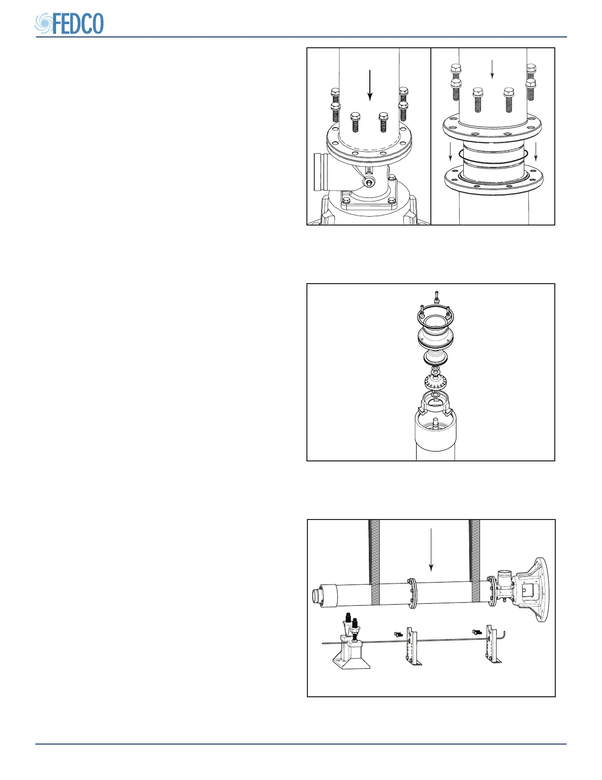
Figure 126 - End Shell Installation
23. Carefully lower the end shell over the stag-
es using safe lifting and handling methods.
Align the end shell ange with the series
shell ange (serial number stamping op-
posite to inlet). Install the shell ange bolts/
lock washers and torque to value specied
in the Fastener Torque Specications sec-
tion of this manual.
NOTES: Make sure there is no gap between
anges after tightening bolts.
Pump Overhaul Continued