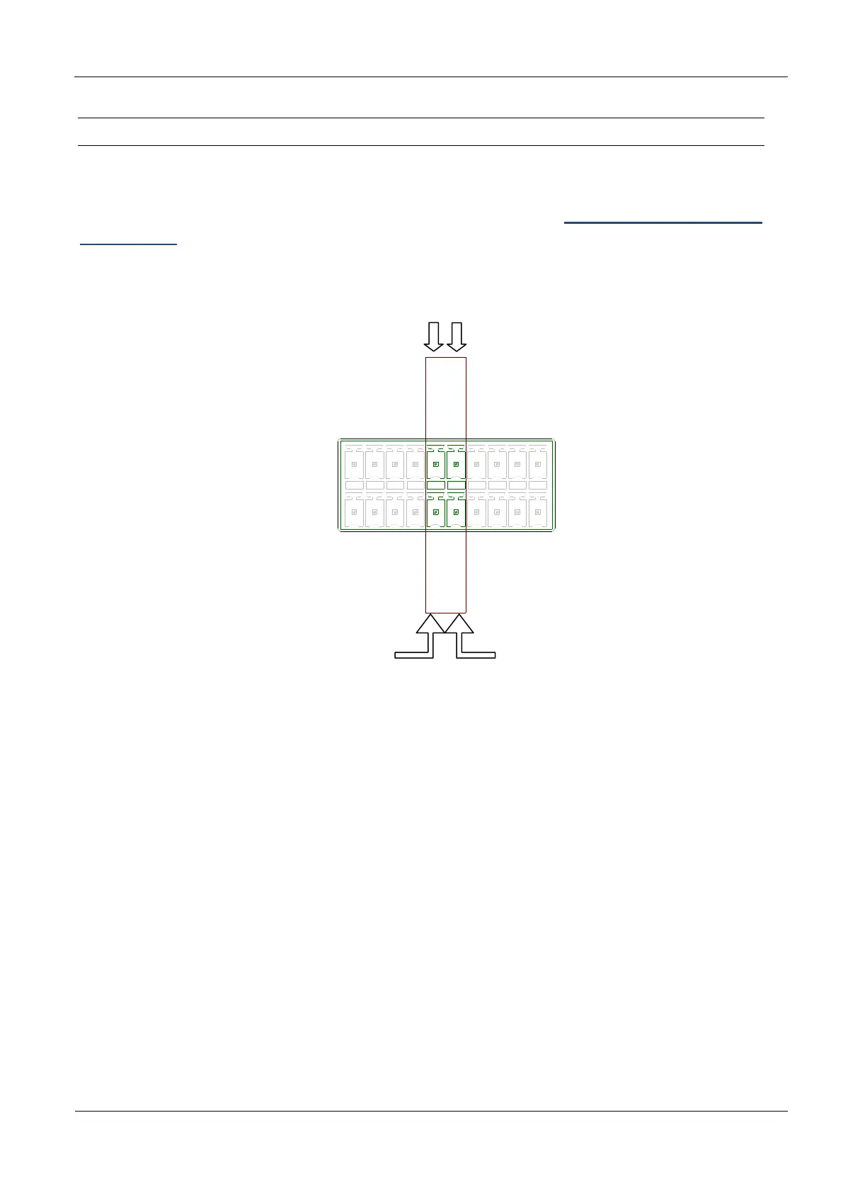
3.11.5 Data-Clock Interface on connector X2
The connection of the data-clock interface take place via the digital Outputs OUT1 and OUT2 at
connector X2. The wire for the “clock” needs to be connected to connector OUT1-C, the wire for
the “data” needs to be connected to connector OUT2-C. See also: Optocoupler outputs (X2 /
OUT1, OUT2)
OUT1-E
IN1-
REL3-COM
REL2-COM
REL1-COM
GND
IN3-
IN2-
GND
OUT2-E
IN1+
OUT1-C
GND
IN3+
IN2+
OUT2-C
REL3-NO
REL2-NO
REL1-NO
24V
X2
Figure 24: Data-Clock Interface on connector X2
NOTE:
The data-clock interface is only available in Scan-Mode.
The data-clock interface cannot be used to configure the reader.
The digital outputs OUT1 and OUT2 are not available, if the data-clock interface is activated.
The data as well as the clock need to be supplied with an external voltage. The output is
configured for max. 24 V DC / 30 mA.
 Loading...