3.6 X2: Optocoupler Inputs (X2 / IN1, IN2, IN3)
The three optocouplers inputs are available on Terminal X2.
X2
IN1-
REL3-COM
REL2-COM
REL1-COM
GND
IN3-
IN2-
GND
OUT2-E
IN1+
OUT1-C
GND
IN3+
IN2+
OUT2-C
REL3-NO
REL2-NO
REL1-NO
24V
OUT1-E
Figure 6: Optocoupler pin-outs on terminal X2
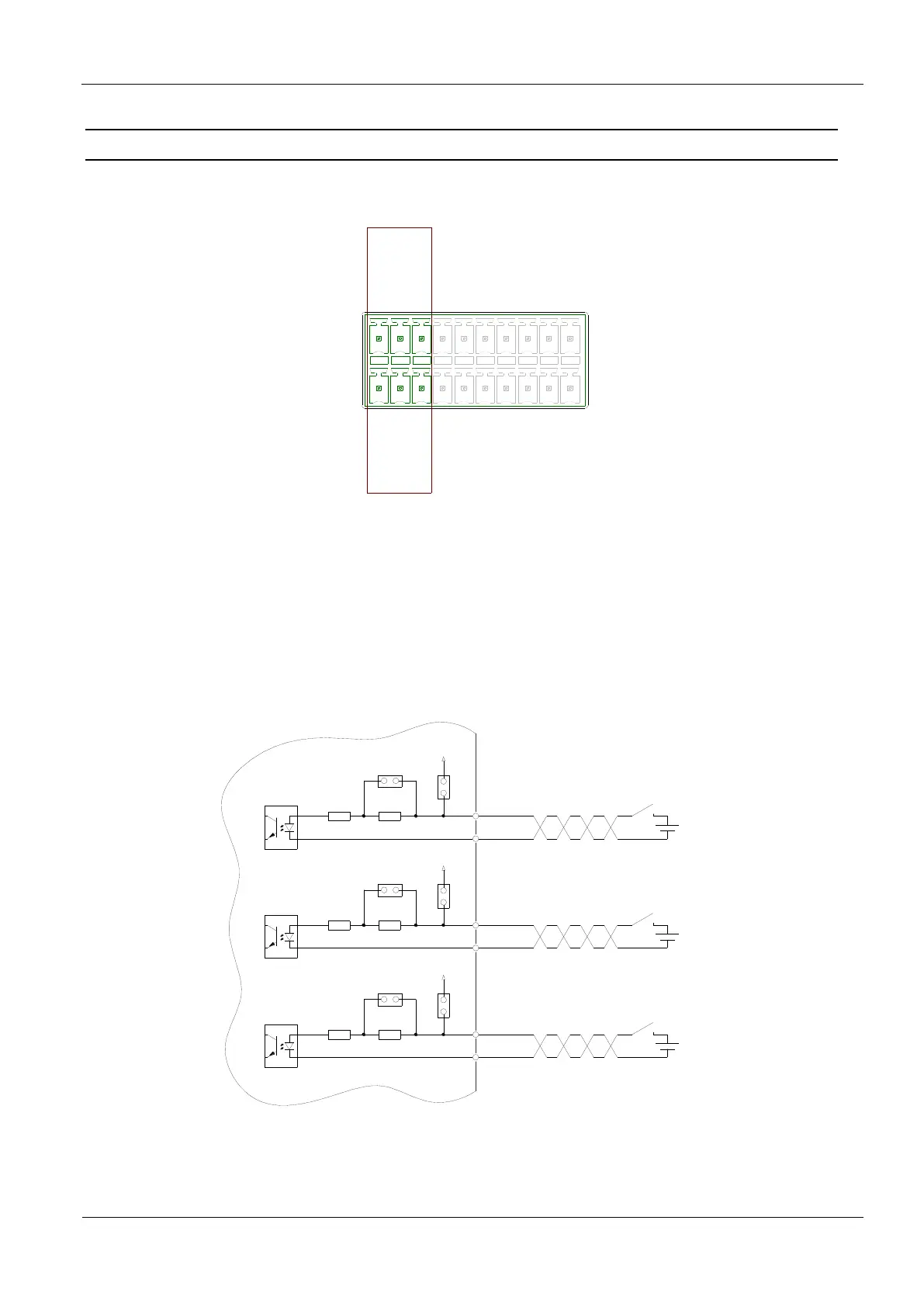
The optocoupler on terminal strips X2 are galvanically isolated from the Reader electronics and
must therefore be powered externally, see Figure 7. The external VCC voltage may however be
provided by the reader, see Figure 8.
All 3 inputs are identical and may therefore be configured individually.
470
+
IN1
-
Uext
820
J2
J1
24 V
470
+
IN2
-
Uext
820
J4
J3
24 V
470
+
IN3
-
Uext
820
J6
J5
24 V
Figure 7: External power supply for the optocouplers on X2
 Loading...