Do you have a question about the Feig Electronic TST WUI and is the answer not in the manual?
Explains document symbols and general cautions for safe operation and handling.
Crucial safety guidelines for personnel and equipment operation that must be followed.
Identifies warnings for personal injury or equipment damage due to improper procedures.
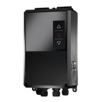
Details housing dimensions, power supply ranges, control voltages, and input requirements.
Specifies requirements for safety chain and emergency stop connections for reliable operation.
Describes safety edge inputs, relay outputs, and drive output specifications.
Covers operating temperature ranges, storage, humidity, and applicable directives.
Emphasizes safe installation practices, including disconnection from mains and ESD precautions.
Guides on proper mounting, sealing cable entries, and avoiding cable strain.
Stresses working in a voltage-free state, residual voltages, and keeping the cover closed.
Instructions for correctly connecting the main power supply to the unit.
Wiring diagrams and instructions for connecting 3-phase and 1-phase motors.
Guides for connecting safety edges, optical systems, and mechanical limit switches.
Reminder to re-check electrical connections before operation to prevent damage.
Procedures for setting the top, bottom, and emergency limit switches for barrier control.
Steps to enter, operate within, and exit parameterisation mode for configuration.
Warning to perform limit switch adjustments only when the system is off or E-STOP is active.
Instructions for connecting photo eye sensors and external control devices.
Details the function of various inputs like door switch, E-stops, limit switches, and sensors.
Explains the functions of the output terminals for TST WUI and TST RWUI controllers.
Steps for starting, selecting, and editing parameters in the controller.
Procedures for saving parameter changes and leaving the parameterisation mode.
Instructions on how to perform a system reset using button combinations.
Describes core gate functions, parameters, and cycle counters.
Details how to access and interpret error memory and diagnostic information.
Lists common error messages, their codes, and potential causes for troubleshooting.
Details errors related to end positions, door movement, maintenance, and safety chains.
Covers further safety chain faults, general hardware issues, and positioning system errors.
Explains internal system errors like voltage issues, E-stop chain faults, and ROM/RAM errors.
Lists internal system errors such as stack errors, parameter checksums, and ROM/EPROM issues.
Lists general information messages indicating operational states like STOP, OPEN, CLOSE.
Provides information messages for deadman, automatic, and parameterisation modes.
Lists messages related to safety edges, RC modules, and induction loop processors.
| Brand | Feig Electronic |
|---|---|
| Model | TST WUI |
| Category | Control Unit |
| Language | English |