TST Startup WUI
FEIG ELECTRONIC GmbH Page 5 of 20 WUI_Inbetriebnahme2_GB.doc
- The parameter setting and operation of the safety equipment must be checked. The adjustment of
the parameters, bridges and other operating elements must only be carried out by qualified staff.
WARNING
Disregarding the safety information can be detrimental to health or damage the
control system.
We do not claim to have fully covered the safety information. Please contact your supplier for further
information about the product.
The manufacturer has carefully tested the appliance hardware and software and the product documentation,
however cannot make any guarantee of complete correctness.
Appliance identification (type plate with information about the name and address of the manufacturer, serial
number, type description, power supply and temperature range) must be done by the user.
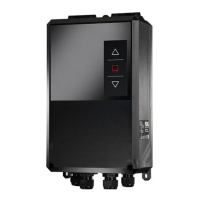
2 Technical data
Housing dimensions (W x H x D): ca.: 182 x 320 x 93mm (without emergency stop button)
Mounting: upright
Power supply range for 3-phase
current with N
3 x 200 ... 415V ±10% / 50 .. 60Hz
corresponds to mains power supply voltage of
115 ... 240V ±10% / 50 .. 60Hz
Power supply range for 3-phase
current without N
3 x 115 ... 240V ±10% / 50 .. 60Hz
corresponds o mains power supply voltage of
115 ... 240V ±10% / 50 .. 60Hz
IMPORTANT
N must be connected with L2.
Power supply range for 3-phase
current without N in connection with
the option
TST WU-0.0-A –
Supply adjustment 400V
3 x 360 ... 400V ±10% / 50 .. 60Hz
Required fuse 3x 10A Type K
Power consumption
Power supply unit without motor
max. 30W
400V 230V 115VPower consumption
Power supply unit with AC3 motor at
Max. 2.2 kW Max. 1.5 kW Max. 0.75 kW
External power supply (230 V):
230 V
AC
±10%, 50...60 Hz
(fused on the printed circuit board: 2 AT)
Control voltage / external power
supply 2:
24 V
DC
±5%
max. 500 mA including all plug-in modules and 12 V connections
fused via self-resetting semiconductor fuse
External power supply 12V:
11.3 VDC ±5%, regulated, max. 150 mA
Control inputs:
IN1 ... IN8:
24 VDC / typ.15 mA
min. signal duration for input control commands: > 100 ms
all inputs must be connected potential-free or:
< 2 V: inactive Æ logical 0
> 17 V: active Æ logical 1
IN9 ... IN10: < 5 V: inactive Æ logical 0
>16 V: active Æ logical 1
Safety chain / emergency stop All inputs must be connected potential-free
< 15 V: inactive Æ logical 0
>17 V: active Æ logical 1
Contact load capacity: ≥ 35 V
DC
/ ≥ 200 mA
If the safety chain is interrupted, no movement of the drive is
possible, not even in deadman