TST Startup WUI
FEIG ELECTRONIC GmbH Page 8 of 20 WUI_Inbetriebnahme2_GB.doc
4 Electrical connection
WARNING
• Connection, testing and maintenance work on
the open control system must only be carried
out in a voltage-free state. You must pay
particular attention to the points mentioned in
the safety information.
• There are still up to 2 minutes of dangerous
voltage after switching off the control system.
• Touching the electronic components is
dangerous due to residual voltages.
• The control system must never be operated
while the housing cover is open.
ATTENTION
• Before switching on the system for the first
time after completing the wiring, it must be
checked whether all motor connections on the
control system and on the motor are tightened
and the motor is switched to star or delta
correctly.
• All control voltage inputs are galvanically
isolated from the power supply by means of a
reinforced insulation. We recommend at least
one additional isolation with a nominal voltage
> 230 V (according to EN 60335-1) for all
components which are to be connected to the
control system.
• Very high electrostatic charges take place
especially for fast-operating rollup plastic
gates. Damage to the control system can result
from this voltage discharge. Therefore, suitable
countermeasures must be taken to prevent
electrostatic charging.
• Maximum cross sections for connection of the
printed circuit board terminals.:
Single
wire
(rigid)
Fine strand
(with/without
wire end
ferrule)
Screw terminals 2.5 1.5
Plug-in terminals 1.5 1.0
Motor terminals 2.5 2.5
Mains connection 2.5 1.5
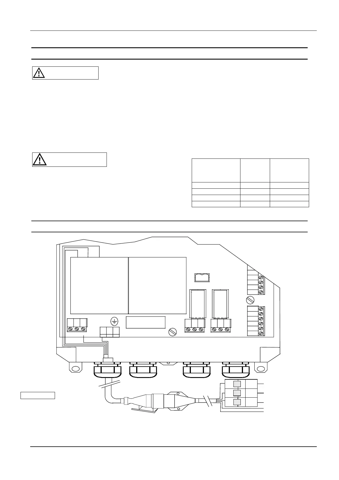
4.1 Power supply connection
CEE plug
5 pole, 16A, red
Fuse
10 A / Type K
PE
N
L1
X10
L1.3
X15X14
X13
-A2T3
N
N
T2T1
PE
14 T2
NT1
T1
T2 T3
T3 14
+A1
L1L2L3
13 L2L1 L3 13
1110
-A2
12 20
K500
X28
1
21 22
K501
+A1
34
X20
3231 33 3635
PE PE
N
PE
L1L2L3
L3.1
extern
41
X22
42
43
L2
L3
Figure 4: Mains cable connection
IMPORTANT
The mains plug must be
visible and accessible
from the control system.