TST Startup WUI
FEIG ELECTRONIC GmbH Page 10 of 20 WUI_Inbetriebnahme2_GB.doc
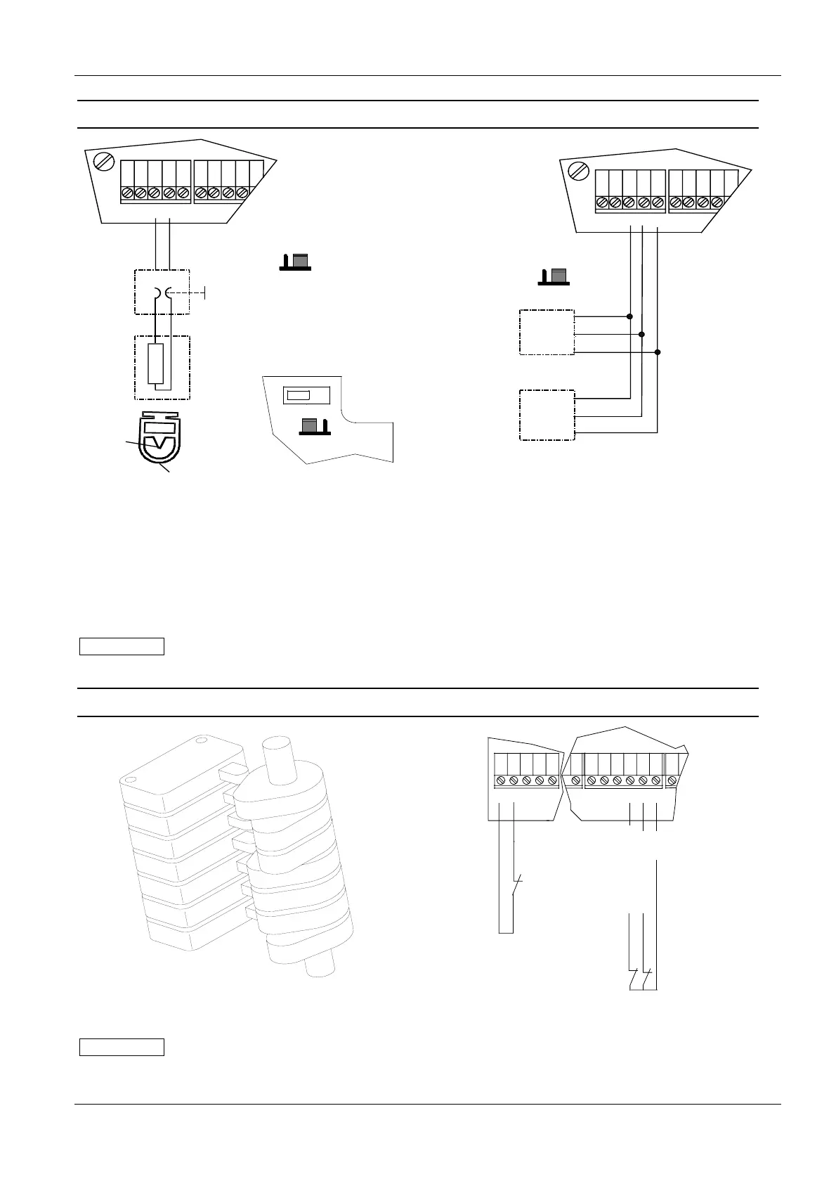
4.4 Safety edge connection
Dynamic optical
systeme
J 400: 1 - 2
41
X22
42 4443 45
51 52 53
X23
J400
8,2K
1,2K
13
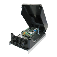
The Jumper
J 400 is
placed in the
upper right
corner of the
PCB
ONOFF
S300
J400
8,2K
1,2K
13
„electric“ safety
edge
J 400: 1 - 2
41
X22
42 4443 45
51 52 53
X23
J400
8,2K
1,2K
13
8k2
Safety
edge
Terminal
resistor
brown
white
Outside
(white)
Inside
(brown)
44
43
Receiver
Trans-
mitter
Green
White
Brown
Figure 7: Safety edge connection
Different types of safety edges can be connected, such as e.g.:
• Electrical safety edge with 1.2kΩ or 8.2kΩ terminal resistor.
• Dynamic optical systems.
If one of these types of safety edges is connected when the TST WU gate control system is switched on, it
will be recognised automatically.
IMPORTANT
If no safety edge is connected, automatic closing of the door is not possible.
It is possible to connect other types of safety edges. Please contact the gate manufacturer for this.
4.5 Limit switch connection
Figure 8: Cam limit switch
41
X22
42
44
43
45 54
62
X24
61
63
71
65
64
66
thermopill
Emergency stop circuit
+24V
Limit switch CLOSE
Limit switch OPEN
Figure 9: Cam limit switch connection
IMPORTANT
Check the electrical connection again before operating the control system.
The appliance can be damaged by wrong connections.