Instruction Manual Radar Motion Detector MWD BP 9/13
Manual MWD BP.doc as 07/21/2006 FEIG ELECTRONIC GmbH
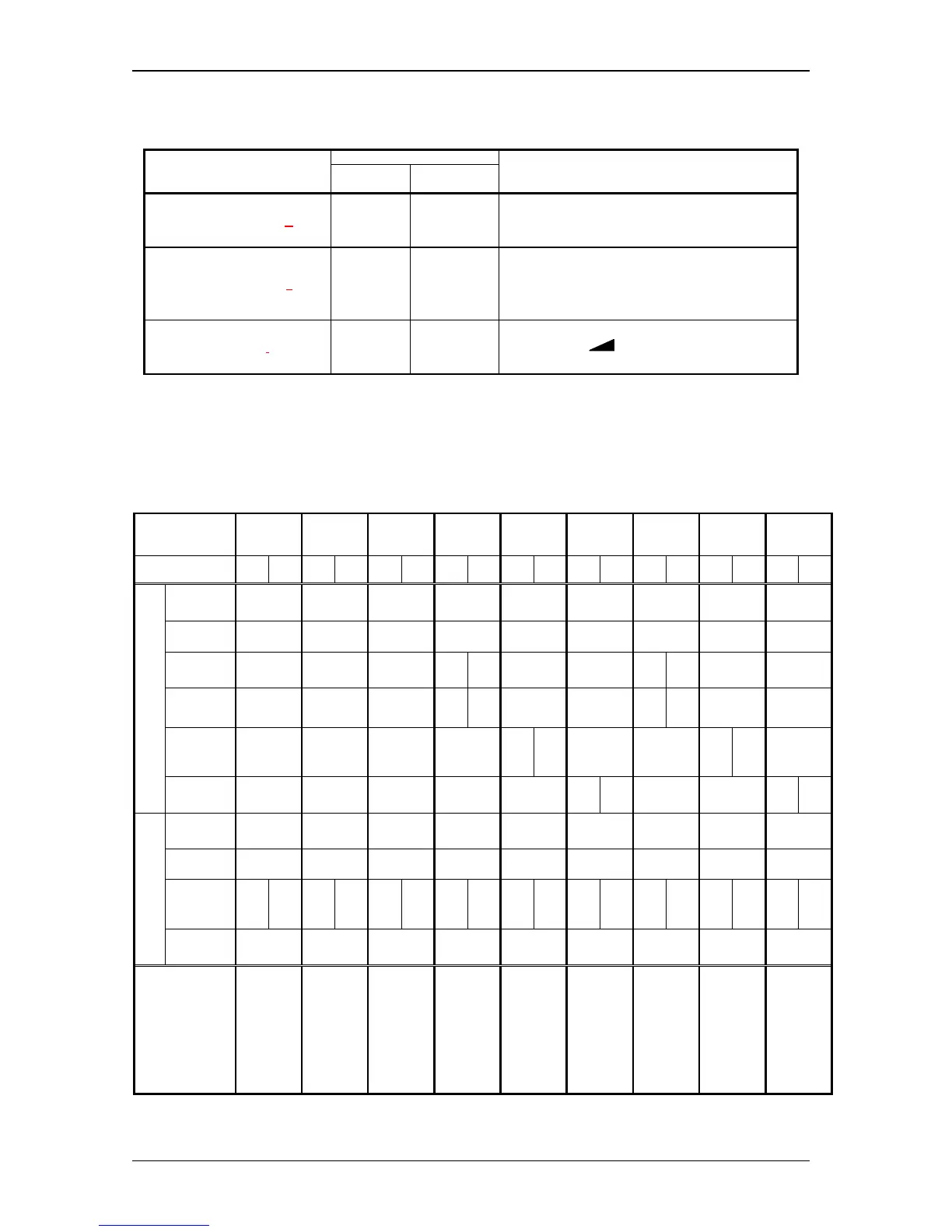
5 Service Parameter List
7-Segment Display
Parameter
Parameter
Name
Value Range
Parameter Definition
device Address
A.
1..9,
b..d
1 = 1 *
: (only odd address)
d = 13
miscellaneous Settings
S.
0..3
0 = all off **
1 = key operation on, display relay output off
2 = only display relay status off **
3 = key operation and display relay output on *
firmware information
i. -
show Firmware-Version on display:
- manually, with „
“-Button for each character
- automatically, with „i“-Button one character per second
* factory setting
** Key operation is always available in the first 15 minutes after power on regardless of the parameter setting. If the display of the relay
output is deactivated, only the decimal point is commonly used to show the relay status of both channels.
6 Profiles
Profile No.
1234 56789
Channel 1 2 1 2 1 2 1 21212121212
Sensitivity
Level
999999999
Direction
appr. appr. appr. appr. appr. appr. appr. appr. appr.
Human
Detection
- - - = 2- - - = 2- - -
Vehicle
Detection
- - --= 2- --= 2- -
Cross
Traffic
Suppr.
- - - - -= 2- - -= 2-
Detection
Object
Tracking
- - - - --= 2- --= 2
On delay
---------
Off delay
400 ms 400 ms 400 ms 400 ms 400 ms 400 ms 400 ms 400 ms 400 ms
Assign-
ments
(Logic)
Ch1 Ch2 Ch1 - Ch1 Ch2 Ch1 Ch2 Ch1 Ch2 Ch1 Ch2 Ch1 Ch2 Ch1 Ch2 Ch1 Ch2
Relay
Working
Principle
AP AP AP AP AP AP RP RP RP
Remarks
Factory
Setting:
additional
parameter
(e.g. device
address =1)
will be
initialized
too.
Channel 2:
Relay output
off
same as
Factory
Setting
without
initializing
additional
parameter
Channel 1 :
only persons
Channel 2 :
only vehicles
Channel 1 :
all objects
Channel 2 :
cross traffic
suppression
Channel 1 :
all objects
Channel 2 :
slow motion
object
tracking
Profile No. 4,
but with RP
Profile No. 5,
but with RP
Profile No. 6,
but with RP
Ch1 = Channel 1 Ch2 = Channel 2
AP = normally de-energized RP = normally energized appr. = approaching direction