Do you have a question about the Fellowes POWERSHRED 3140 Series and is the answer not in the manual?
Clean the exterior of the shredder with a soft cloth using a mild detergent solution.
Perform maintenance tasks like removing paper strips and dusting lubricated/non-lubricated surfaces.
Visually inspect the shredder for defects such as loose screws, terminals, and connectors.
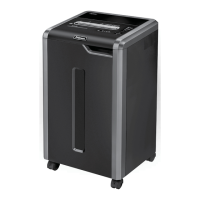
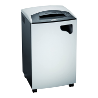
Describes the Power and Reverse functions of the shredder's control panel button.
Explains the function of the three indicator LEDs: Door open and Safety Flap status.
Addresses issues like paper jams due to misfeeds, full bins, or debris in the cutting assembly.
Covers common electrical faults like door issues, loose wires, defective PC boards, bin full system, and ECC.
Identifies mechanical faults by listening to noise and observing cutting capacity drops.
Comprehensive list of hand tools, lubricants, and consumables needed for shredder maintenance and repair.
Step-by-step guide to opening and accessing the self-contained shredder head unit.
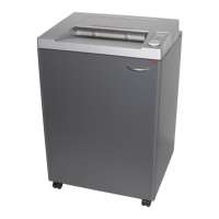
Details on removing the cabinet door, waste bin, and castors from the shredder.
Overview of the gear drive, motor, and cutting block as key mechanical components.
Explains capacitor function, common problems caused by defects, and replacement steps.
Instructions for removing the power cord, including unplugging wires and loosening strain relief.
Details the snap action switch activated by a flap to monitor the waste bin's fullness.
Information on the main PC board's location, securing screws, wire disconnections, and replacement procedure.
Details the power relay board's function, location, securing screws, and replacement considerations.
Visual representation of how the PC boards, motor, capacitors, and sensors are wired together.
Explains the function of I/R sensors and procedures for replacing them.
| Brand | Fellowes |
|---|---|
| Model | POWERSHRED 3140 Series |
| Category | Paper Shredder |
| Language | English |