EasyManua.ls Logo

Fender BASSBREAKER 007 Combo User Manual

Fender BASSBREAKER 007 Combo
16 pages
To Next Page IconTo Next Page
Page #1 background imageLoading...
Page #1 background image
BASSBREAKER007
(This is the model name for warranty claims)
Fender Musical Instruments Corp. / 17600 North Perimeter Drive, Suite 100 / Scottsdale, AZ 85255-5440
Issued October, 2015
p/n 2262000000 (COMBO 120V)
p/n 2263000000 (HEAD 120V)
SERVICE MANUAL
ATTENTION:
WARRANTY SERVICE PROCEDURES
The Bassbreaker 007 Amplifier is considered to be field serviceable to the component level.
As such stuffed PCB Assemblies are not readily available for this unit. Any Fender Authorized
Service Center in need of a warranty replacement PCB Assembly for this unit should contact
FMIC Tech Support and you will be instructed on how to proceed.
Question and Answer IconNeed help?

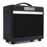
Do you have a question about the Fender BASSBREAKER 007 Combo and is the answer not in the manual?

Fender BASSBREAKER 007 Combo Specifications

General IconGeneral
BrandFender
ModelBASSBREAKER 007 Combo
CategoryAmplifier
LanguageEnglish

Summary

Warranty Service Procedures Attention

Warranty Service Procedures Attention

Important notice regarding warranty service procedures for component-level repair.

Important Notice and Copyright

Parts List Codes Definition

Bassbreaker 007 Specifications

Service Notes and Disassembly Procedures

Chassis Removal Procedure

Step-by-step instructions for removing the chassis from the amplifier cabinet.

Rear Panel I/O PCB Assembly Removal

Procedure for safely removing the rear panel input/output PCB assembly.

Top Panel Control PCB Assembly Removal

Steps to remove the top panel control PCB assembly for component access.

Tube PCB Assembly Removal

Instructions for removing the tube PCB assembly, noting potential need to remove PSU PCB.

Power Supply PCB Assembly Removal

Guide to removing the power supply PCB assembly, often with the tube PCB.

PCB Exchange Policy

Circuit Description Overview

Pre-Amplifier Circuit Description

Detailed description of the pre-amplifier stages, including gain and tone controls.

Power Amplifier Circuit Description

Explanation of the single-ended Class-A power amplifier stage and output transformer.

Power Supply Circuit Details

Footswitch Control Mechanism

PCB Assembly Parts List

Chassis Assembly Parts List

Combo Cabinet Assembly Parts List

Head Cabinet Assembly Parts List

Combo End Item Assembly Parts List

Head End Item Assembly Parts List

Related product manuals