EasyManua.ls Logo

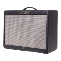
Fender BASSBREAKER 15 Combo User Manual

Fender BASSBREAKER 15 Combo
22 pages
To Next Page IconTo Next Page
Page #1 background imageLoading...
Page #1 background image
BASSBREAKER™ 15
(This is the model name for warranty claims)
Fender Musical Instruments Corp. / 17600 North Perimeter Drive, Suite 100 / Scottsdale, AZ 85255-5440
Issued June, 2016
p/n 2262000000 (COMBO 120V)
p/n 2263000000 (HEAD 120V)
SERVICE MANUAL
ATTENTION:
WARRANTY SERVICE PROCEDURES
The Bassbreaker 15 Amplifier is considered to be field serviceable to the component level. As
such stuffed PCB Assemblies are not readily available for this unit. Any Fender Authorized
Service Center in need of a warranty replacement PCB Assembly for this unit should contact
FMIC Tech Support and you will be instructed on how to proceed.
Question and Answer IconNeed help?

Do you have a question about the Fender BASSBREAKER 15 Combo and is the answer not in the manual?

Fender BASSBREAKER 15 Combo Specifications

General IconGeneral
Power Output15 Watts
Speaker1 x 12"
Channels2
Effects LoopYes
Inputs1 x 1/4"
Cabinet MaterialPlywood
TypeTube
ControlsBass, Middle, Treble, Gain
EffectsReverb
Outputs1 x 1/4" (speaker)
FootswitchOptional
Tubes2 x 12AX7, 2 x EL84

Summary

Warranty Service Procedures

Attention: Warranty Service Procedures

Important notice regarding field serviceability and PCB replacement procedures.

Important Notices and Safety Precautions

Service Notes and Disassembly Procedures

General Disassembly and Wire Dress Guidelines

Guidance on proper wire dress, taking photos, and general disassembly steps.

Chassis, Rear Panel, and Front Panel PCB Removals

Procedures for removing chassis, rear panel, input, speaker jack, impedance, gain, and control PCBs.

Component and PCB Removal Procedures

Circuit Description - Signal Path Details

Power Amplifier Design and Output

Describes the power amp, phase inverter, and output transformer.

Power Supply and Mute Functionality

Power Supply Circuit Description

Details the power supply circuitry, including voltage regulation and filament drive.

Schematic Diagram - Key PCB Sections

Input, Tube, and Gain Control PCBs

Details the schematic for Input, Tube, and Gain Control PCBs, including test points.

Power Supply and Rear Panel PCBs

Details the schematic for Power Supply and Rear Panel PCBs, including test points.

Speaker and Impedance Switch PCBs

Details the schematic for Speaker and Impedance Switch PCBs, including feedback loop.

Test Conditions and Notes

Provides maximum output test conditions, voltage measurement notes, and general parameters.

Schematic Diagram - Power and Fuses

PCB Assembly Diagram - Component Layout

Component Placement and Layout

Shows the physical layout of components on the PCB assemblies.

Assembly Notes and Test Points

Provides notes on PCB assembly and identifies key test points.

Schematic Diagram - Signal Path Details

Signal Path and Test Points

Details specific signal paths and test points across various PCBs in the schematic.

Related product manuals