Installation & Operating Instructions
ııııııııııııııııııııııııııııııııııııııııııııııııııııııııııııııııııııııııııııııııııııııııııııııııııııııııııııııııııııııııııııııııııııııııııııııııııııııııııııııııııııııııııııııııııııııııııııııııııııııııııııııııııııııııııııııııııııı
Page 13
www.fptgroup.com
Fenner is a registered trademark of J.H. Fenner & Co. Limited
ııııııııııııııııııııııııııııııııııııııııııııııııııııııııııııııııııııııııııııııııııııııııııııııııııııııııııııııııııııııııııııııııııııııııııııııııııııııııııııııııııııııııııııııııııııııııııııııııııııııııııııııııııııııııııııııııııııı
Page 12
www.fptgroup.com
Fenner is a registered trademark of J.H. Fenner & Co. Limited
Installation & Operating Instructions
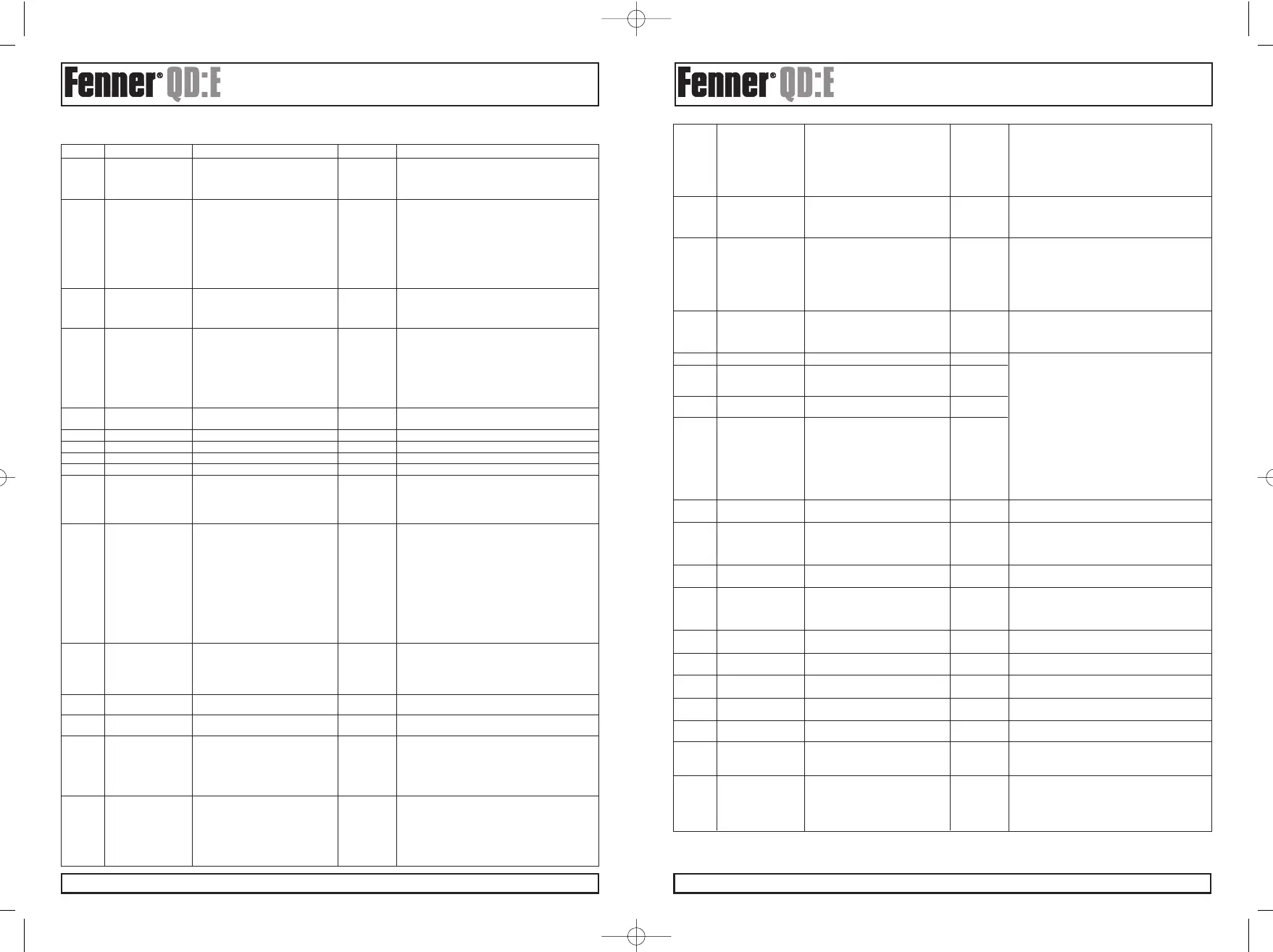
7.1. STANDARD PARAMETERS
Par. Description Range Default Explanation
Defines the function of the digital inputs depending
P-15
Digital input
0 to 12 0
on the control mode setting in P-12.
function selec See section 8 Analog and Digital Input
Configurations for more information.
Configures the voltage or current format of the
analog input signal.
b 0..10V can be used for bipolar input signals. A
0..10V, b 0..10V, 0..20mA, 50% offset can be applied to P-39 and 200%
P-16 Analog input format t 4..20mA, r 4..20mA, 0..10V scaling in P-35 gives ± P-01
t 20..4mA r 20..4mA “t” indicates the drive will trip if signal removed
when drive is enabled.
“r” indicates the drive will ramp to Preset Speed 1
if signal is removed when drive is enabled
Sets maximum effective switching frequency of the
P-17 Effective switching 4 .. 32kHz 8 / 16kHz drive. If “rEd” is displayed, the switching frequency
frequency has been reduced to the level in P00-14 due to
excessive drive heatsink temperature.
0 : Drive enabled Defines the function of the user relay, when the
1 : Drive healthy operating conditions are met.
2 : Motor at target speed Disabled : Contacts open
P-18 User relay output 3 : Drive tripped Enabled : Contacts closed
select 4 : Motor speed >= limit 1
5 : Motor current >= limit Options 4 to 7: the Relay output is enabled using
6 : Motor speed < limit the level set in P-19
7 : Motor current < limit
P-19
User relay output 0.0 to 100% for speed
100%
Sets the limit for P-18 & P-25
limit 0.0 to 200% for current
P-20 Preset speed 1 -P-01 to P-01 0 Hz Sets jog / preset speed 1
P-21 Preset speed 2 -P-01 to P-01 0 Hz Sets jog / preset speed 2
P-22 Preset speed 3 -P-01 to P-01 0 Hz Sets jog / preset speed 3
P-23 Preset speed 4 -P-01 to P-01 0 Hz Sets jog / preset speed 4
2nd Deceleration ramp time from base speed (P-09)
P-24
2nd decel ramp time to standstill in seconds.
(Fast Stop) 0…25.0s 0 Selected using fast stop function via digital input
setting or on mains loss as set by P-05
If set to zero drive will coast to STOP.
Digital output mode Digital Output Mode
0 : Drive enabled Options 0 to 7 select a digital voltage output signal
1 : Drive healthy Disabled : 0V
2 : Motor at target speed Enabled : +24V, (20mA limit)
3 : Drive tripped Options 4 to 7 : the Digital output is enabled using
P-25 Analog output 4 : Motor speed >= limit 8 the level set in P-19
function select 5 : Motor current >= limit Analog Output Mode
6 : Motor speed < limit Option 8 : Motor Speed signal range
7 : Motor current < limit 0..10V = 0..100% of P-01
Analog output mode Option 9 : Motor Current signal range
8 : Motor speed 0..10V = 0..200% of P-08
9 : Motor current
Set P-09 before adjusting.
Skip frequency
Speed reference held at upper or lower skip
P-26
hysteresis band
0 to P-01 0 Hz frequency limit until input signal reaches the
opposite skip frequency limit. Speed ramps through
the skip frequency band at a rate set by P-03 and P-04.
P-27
Skip frequency P-02 to P-01
0 Hz
Set P-09 before adjusting.
Skip frequency centre point
P-28
V/F characteristic
0 … P-07 0
Adjusts the applied motor voltage to this value at
adjustment voltage the frequency set in P-29
Sets the frequency at which the adjustment voltage
set in P-28 is applied
0 … P-09
0.0Hz
Edge-r : if drive is powered up with Digital Input 1
P-29
V/F characteristic
closed (enabled), drive will not run. The switch must
frequency adjust
be opened & closed after power up or after clearing
a trip for the drive to run.
Auto-0 : drive will run whenever digital input 1 is
closed (if not tripped).
Terminal mode Auto-1..5 : drive will make 1..5 attempts to
P-30
restart function EdgE-r, Auto-0 .. Auto-5 Auto-0 automatically restart after a trip (25s between
attempts). If fault has cleared drive will restart. To
reset the counter the Drive must be powered down,
reset on the keypad or by re-enabling the drive.
If set to 0 or 2, drive will always start from
0 : Minimum speed minimum speed.
Keypad mode 1 : Previous speed If set to 1 or 3, drive ramps up to the operating
P-31 restart function 2 : Minimum speed (Auto-run) 1 speed prior to the last STOP command.
3 : Previous speed (Auto-run) If set to 2 or 3, the status of digital input 1 controls.
drive to start or stop. The start and stop button on
the drive will not function in this case.
When > 0, DC injection braking activated when
0 to 25.0s 0 speed reaches zero with stop signal applied.
P-32
DC injection on stop (disabled) Only applied on disable (Stop), not on enable.
Uses the level set in P-11.
When enabled, drive starts from detected motor
rotor speed. Short start delay possible if rotor
Spin Start 0 : Disabled stationary. Recommended for high inertia load
P-33 (S2 & S3 only) 1 : Enabled 0 applications.
DC injection on For Size 1 drives, P-33 = 1 enables DC injection
start (S1) braking on enable. The duration and levels are set
by P-32 and P-11 respectively.
Brake chopper Software protection for Fenner standard brake
P-34
enable (not S1) 0 : Disabled resistors (200W).
1 : Enabled with s/w protection For Non-Fenner approved resistors and higher
2 : Enabled without s/w protection 0 braking applications set to 2.
P-35 Analog input scaling 0 … 500.0% 100% Analog input scaling, resolution 0.1%.
Serial Adr : 0 disable, 1..63 Adr : Unique drive address for communication
Communications 1 network
address When set to OP-buS, MODBUS disabled.
MODBUS enable / OP-buS (fixed at 115.2 kbps) 0P-buS Communication with PDA, PC and QPort:E
baudrate select 9.6k to 115.2kbps (Modbus) possible
Setting a baudrate enables MODBUS at that
baudrate and disables OP-buS.
0 (no trip) t 3000 The time before a trip in the event of a
P-36 Trip enable / delay t 30, 100, 1000, 3000 (ms) (3 second trip) communication loss can be set in milliseconds.
r 30, 100, 1000, 3000 (ms)) Setting “0” disables the communications trip.
“t” indicates the drive will trip if time exceeded.
“r” indicates the drive will ramp to stop if time
exceeded.
P-37
Access code
0 to 9 999
101
Defines Extended Parameter Set access code, P-14
definition
0: Parameters can be changed &
Controls user access to parameters. When P-38 = 0,
P-38
Parameter access
automatically saved on power down
all parameters can be changed and will be stored
lock
1: Read-only. No changes allowed.
0
automatically. When P-38 = 1, parameters are
locked and cannot be changed.
P-39 Analog input offset -500.0 … 500.0% 0%
Introduces an offset to the analog input level with a
resolution 0.1%. e.g. 10% = 1V = 0Hz
Custom scaling factor applied to drive speed. If P-10
P-40
Display speed
0.000 to 6.000
= 0, speed in Hz scaled by this factor. If P-10 > 0,
scaling factor speed in RPM scaled. Displayed as real-time
variable on the drive display, indicated by a “c”.
P-41
User PI Proportional
0.0 ... 30.0 1.0
Higher value used for high inertia. Too high a value
Gain gives instability.
P-42
User PI Integral
0.0s ... 30.0s 1.0s Higher value gives slower, more damped response.
time constant
P-43
User PI operating 0: Direct 0 If an increasing feedback signal should increase the
mode 1: Inverse speed of the motor, set to ‘Inverse’ mode.
P-44
User PI reference 0: Digital Sets the source for the PI control reference signal.
select 1: Analog
0
When set to 1, analog input 1 is used.
P-45
User PI digital
0 … 100% 0.0 % Sets the preset reference used when P-44 = 0.
reference
User PI feedback 0 : 2nd analog input (T4)
P-46 select 1 : 1st analog input (T6) 0 This parameter selects the feedback signal source.
2 : motor load current
Selects the format of the 2nd analog input.
2nd analog input 0..10V, 0..20mA, “t” indicates the drive will trip if signal removed
P-47 format t 4..20mA, r 4..20mA, 0 ..10V when drive is enabled.
t 20..4mA r 20..4mA “r” indicates the drive will ramp to Preset Speed 1
if signal is removed when the drive is enabled
 Loading...