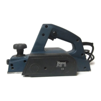
Bevelling edges
The V-groove in the planer shoe allows easy
beveling of workpiece edges. Place the planer
with the V-groove (K) onto the edge of the
workpiece and guide along the edge.
Rebating
The rebating depth stop can be used by planing
for example a window- or doorpost. Loosen the
locking nut and adjust the required rebating depth
with the scale (Fig.2, H). Carry out the the planing
procedure several times (guide the planer with
sideward supporting pressure), until the required
rebating depth is reached. The maximum rebating
depth is 18 mm.
Warning!
• Takecarethatyourhandnevercomesin
contact with the work piece during the
operation.
• Onlyusetheelectricplaneontheupperside
of the work piece, never from below or from
the side.
• Storetheapplianceonlyafterithascometoa
complete standstill.
• Useasuctiondevicetosuckoffwood
shavings or dust. For this use the connecting
pipe (Fig. 2, L accessories) and connect a
suction pipe to it.
• Useaholdingdevicetoworkonsmallwork
pieces.
Fitting the rip fence
Fig. 4
• Loosenknob(M).
• Inserttheripfenceintotheslotsprovided.
• Setthecorrectcutwidthandtightentheknob
(M+N).
4. Care and maintenance
Before undertaking any care or
maintenance always remove the mains
plug from the socket.
The planing tool becomes worn after a period of
operation. If you use a blunt or damaged planing
tool operational efficiency is reduced and the
electric motor might become overloaded. Check
the planing tool regularly with regard to wear or
damage. Depending on its condition, the planing
tool will have to be replaced.
Removal of plane blade
Fig. 3
Usetheenclosedopen-jawedspanner
(Accessories). First unscrew the three clamping
screws (6) with the open-jawed spanner and
remove the plane blade (3), the plane blade holder
(2) and the plane blade support (4) from the
holding shaft (1).
Installation of plane blade
Fig. 3
Take the new plane blade (3) and position it
between the plane blade support (4) and the plane
blade holder (2). Now turn the clamping screws (6)
as far as possible into the plane blade support. But
not so far that the plane blade and the plane blade
holder become detached again from the plane
blade support. Afterwards put the plane blade,
plane blade holder and plane blade support
together into the holding shaft. The plane blade
support, plane blade and plane blade holder will
now be fastened together in the holding shaft by
releasing the clamping screws with the open-
jawed spanner and thus the plane blade, plane
blade support and plane blade holder are clamped
in position.
Attention!Unscrewclampingscrewsasfasas
possible so that a sufficient attachment is ensured.
Warning!
• Wheninstallingandremovingtheplaneblade,
care has to be taken that all parts (plane
blade, plane blade holder, plane blade support
and holding shaft) are clean. Dirt or possible
existing layers of dirt have to be removed.
• TheAllenscrews(5)aresecuredwithan
adhesive. These screws must not be adjusted.
The position of these screws may only be
altered by the manufacturer!
Check regularly if the clamping screws
are tightened firmly. Always tighten
screws firmly.
Corrective action in case of failure
1. The operating switch is switched on, but
the motor is not working.
 Loading...