Pag 30
FINGERPRINTFINGERPRINT
FINGERPRINTFINGERPRINT
FINGERPRINT
FINGERPRINTFINGERPRINT
FINGERPRINTFINGERPRINT
FINGERPRINT
ON
512 43678
Bs
Aux
Sp C No-
ON
512 43678
PC CONNECTORA B
CN3
DESCRIPTION
CN4 DISPLAY
KEYPAD
CONNECTOR
8
STAND ALONE
CENTRALIZEDOFF
SW1
ON
-+
Bs
-
Sp
CN4
CN3
SW1
UP
12V
Aux ADt Ck R G B No C Nc
B
MÓDULO LECTOR DE HUELLA CON PROXIMIDAD
FINGERPRINT READER & PROXIMITY MODULE
AUTÓNOMO
STAND ALONE
8: ON
Vac
12Vac / 12Vdc
Guía rápida de programación
Add Users:
- 1 Fingerprint Mode (1 fingerprint)
- 2 Fingerprint Mode (2 fingerprints)
- Card
Delete user:
- Per user number
- Full reset of all users
Time Configuration:
- Lock-Release Timing
- Door Sensor Timing
- Alarm Time (auxiliary output)
Auxiliary Output Time
- No function activated
- Door and door forced open alarm
- Intruder Alarm (incorrect fingerprint)
Add
d1.1/d1.2 - rela/both/Au
d2/d2.1- rela/both/Au
leds-card-Prox
ErA
000
ALL
TeM
t. Ab
t. SE
t. AL
AU
- - -
ALP
ALI
Function Code
Molex connectors:
molex connection display: +, -, D, C
molex connection keypad: +, -, Pl, Ck, Si, -, Vl
Dip-switch: to select the reader and system addresses: autonomous or centralised.
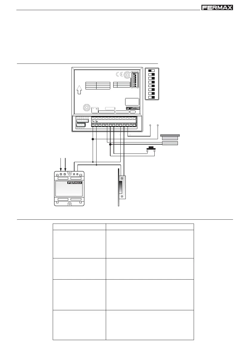
Wiring Diagram
AUXILIARY
OUTPUT
OUTPUT BUTTON
DOOR
SENSOR
POWER SUPPLY
LOCK-RELEASE
12Vac / 12Vdc
Function Description
 Loading...