VDSVDS
VDSVDS
VDS
VDSVDS
VDSVDS
VDS
Page 17
Code 97508I-1 V07_09
+, - 18Vdc power supply.
L: audio + data bus
V, M: video terminals: V: live; M: mesh (only in video amplifier).
+12: Auxiliary voltage output (12Vdc, 0.4A max).
C, NO, NC: Potential-free door lock-release relay (4A). Activates alternating lock release (if the system is
equipped with this source), magnetic locks, signals to other devices, etc.
BS, -: Button connection to open door from inside the entrance hall.
S: Activation signal which gives a negative result when the panel is activated after a call or autostart.
CT: Camera activation signal or auxiliary output (11 Vdc). Configurable using the JP4 switch.
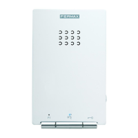
Amplifier Version.
Connection Terminals:
12
11
SW1 Mapping: button to enter switch programming mode (see the Advanced Programming - Mapping
section).
10
* Restore factory settings. Reset
The VDS amplifier has a ‘Reset’ function which can be used to restore programmed default parameters (door and
hall lock-release times, access codes, mapping).
- Reset from button panels
To restore the default values, follow the steps below:
1.- Reset amplifier: disconnect power supply
2.- Press the SW1 button, connect power supply and keep SW1 button pressed until you hear the reset confirmation
sound.
- Reset from keypad panels
To restore the default values, follow the steps below:
1.- Reset amplifier: disconnect power supply
2.- Connect power supply and within the first 60 seconds, enter the code A708B9. After entering the code, a
prolonged beep will sound to confirm the restoration of default values.
9
MIC: Microphone connections (microphone is located in the interior panel profile).
8
Audio volume adjustment in residence-entry panel direction.
Audio volume adjustment in entry panel - residence direction.
Controls for audio adjustments:
Volume adjustment for call monitoring and voice synthesis.
Diagnostic Led: If there is a short circuit between “L” and “+”, short flashes will be emitted when a call is
made from the panel.
L
* Technical Features
Consumption:
Operating Temperature
Maximum audio power in the residence -entry panel direction
18 Vdc
on standby
active audio
audio + video
-10 , +60 °C
57 mA
300 mA
380 mA
Maximum audio power in the entry panel - residence direction.
Power Supply
2 W
0.15 W