Installation and Maintenance Manual form 185
Page 3
1.3 DETERMINING PROPER LOCATION –
PLANING VESSELS
1.3.1 For planing hull vessels, locate the unit as far aft as
possible to avoid aeration and impact shock in heavy
seas.
1.4 IMPROPER (NOT RECOMMENDED)
LOCATIONS
1.4.1 The area of the hull where the GRIDCOOLER® Keel
Cooler is installed must not vibrate or flex severely.
1.4.2 To eliminate unnecessary stress and vibration on the
cooler, do not locate the unit directly below engine
mounts or above the propeller(s).
1.4.3 Make sure that hot water is not discharged on or
near the unit.
1.4.4 Do not locate the unit on the front 1/3 of the hull for
displacement hulls. Bowthruster coolers could be an
exception, depending on the vessel.
1.4.5 The GRIDCOOLER Keel Cooler is designed to be
mounted directly to the hull. Do not mount the unit
to any external structure without first consulting the
factory.
1.5 MOUNTING CONSIDERATIONS – TYPICAL
1.5.1 Some classed vessels (ABS or Coast Guard, for
example) may require coerdams, check with your
local ocials for more information. For this type of
installation, see Coerdam Installation in Section 3.1.
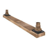
1.5.2 The GRIDCOOLER unit can be canted from the hull
(sideways) to vertically align the nozzles. This can
reduce interference problems with stringers on
coerdam installations. See Figure 4. (referred to
section 3.1 for coerdam installation)
FIG.4 Canted Installation with Coerdam.
1.5.3 If the unit is recessed into the hull, make sure that
there is 1-1/2 in. (38 mm) minimum clearance on all
sides (this does not include between the hull and the
top of the cooler). The recess should be no deeper
than 1/2 in. (13 mm) plus the hull projection (listed on
installation drawing) of the cooler.
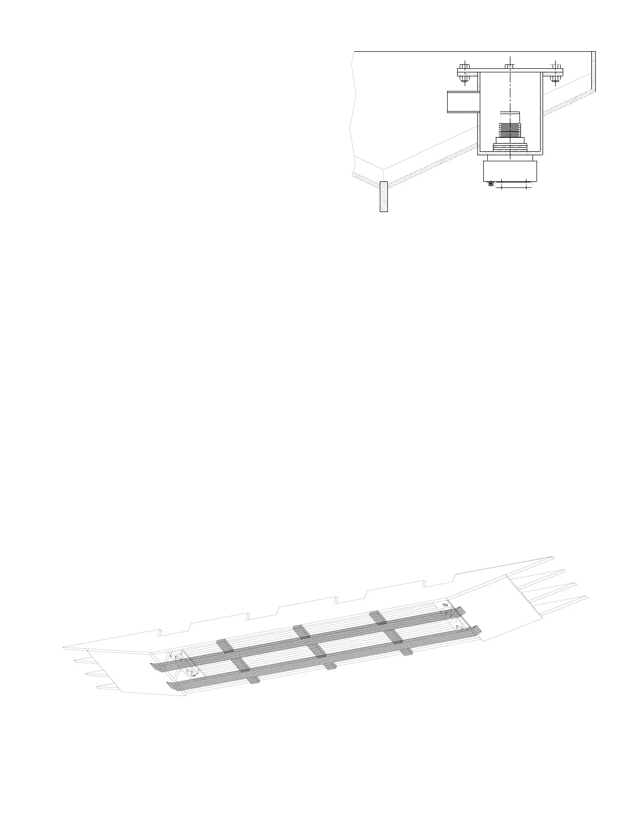
1.5.4 In extreme cases, where logs, debris, or dragging
bottom may endanger the unit, a protective guard
may be mounted over the unit. Make certain the
guard does not cover more than 25% of the face
opening. For examples of protective guards and
dierent installations that have been used, see
Figures 5 and 6.
FIG.5 Example of external guarding